Hyundai Palisade (LX2): Integrated Body Control Unit (IBU) / IMS Control Switch
Components and components location
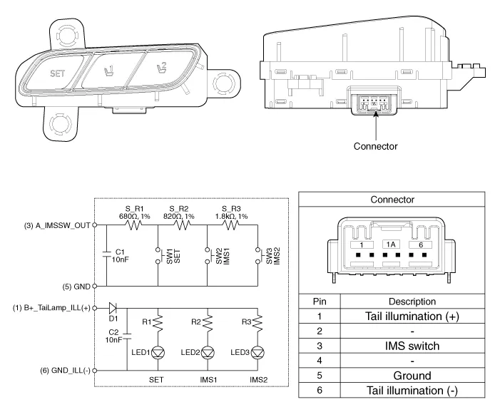
| Components |
Repair procedures
| Inspection |
| 1. |
Disconnect the IMS control switch connector.
|
| 2. |
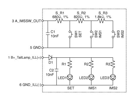
With the power IMS control switch in each position, make sure that continuity
exists between the terminals below. If continuity is not as specified,
replace the IMS control switch.
|
| Removal |
| 1. |
Disconnect the negative (-) battery terminal.
|
| 2. |
Remove the front door trim.
(Refer to Body - "Front Door Trim")
|
| 3. |
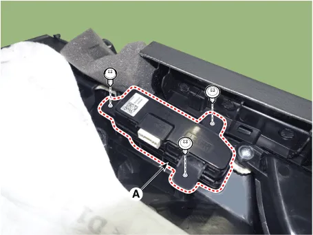
Disconnect the IMS switch connector (A) and then remove the IMS switch
(A).
|

| Installation |
|

| 1. |
Connect the connectors and reassemble the IMS control switch.
|
| 2. |
Reassemble the front door trim.
|
| 3. |
Connect the negative (-) battery terminal.
|
Components and components location Components IMS input/output pin information No Connector A Connector B Connector C 1 Cushion extension moter (Front) B+ (Power) Seat slide motor switch (Front) 2 Seat recline motor (Front) Ground (Power) Seat recline switch (Front) 3 Seat height motor (Up) B+ (Power) Seat tilt switch (Up) 4 Seat slide motor(Front) - Seat height switch (Up) 5 Seat Cushion extension moter (Rear) Ground Seat cushion extension switch (Front) 6 Seat recline motor (Rear) B_CAN (High) 7 Seat tilt motor (Up) B_CAN (Low) 8 Seat tilt motor (Down) Lumber motor (Up) 9 Seat height motor (Down) Lumber motor (Down) 10 Seat slide motor (Rear) Seat slide sensor 11 Seat tilt sensor 12 - 13 Seat position sensor power 14 IGN 1 15 Seat slide switch (Rear) 16 Seat recline switch (Rear) 17 Seat tilt switch (Down) 18 Seat height switch (Down) 19 Seat cushion extension switch (Rear) 20 Ground 21 Lumber motor (Low) 22 IMS switch 2 23 - 24 Seat recline sensor 25 Seat height sensor 26 - 27 - 28 Battery (+) Repair procedures Removal 1.
Other information:
Hyundai Palisade (LX2) 2020-2026 Service Manual: Auto Defogging Sensor
Description and operation Description The auto defogging sensor is installed on the front window glass. The sensor judges and sends signal if moisture occurs to blow out wind for defogging. The air conditioner control module receives signal from the sensor and restrains moisture and eliminate defog by controlling the intak
Hyundai Palisade (LX2) 2020-2026 Service Manual: Rear Corner Radar Unit
Specifications Specifications [BCW, BCA] Items Blind-Spot Collision Warning (BCW) Blind-Spot Collision- Avoidance Assist (BCA) Rated voltage DC 12V Operating voltage 9V - 16V Operating speed 30 km/h
Categories
- Manuals Home
- Hyundai Palisade Owners Manual
- Hyundai Palisade Service Manual
- General Tightening Torque Table
- Rear Heater Unit
- Engine Mechanical System
- New on site
- Most important about car
