Hyundai Palisade (LX2): Front Suspension System / Front Stabilizer Bar
Repair procedures
| Removal |
| 1. |
Turn the ignition switch OFF and disconnect the battery negative (-)
cable.
|
| 2. |
Turn the steering wheel so that the front wheels are placed in the straight
ahead position.
|
| 3. |
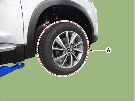
Remove the front wheel and tire (A) from front hub.
|

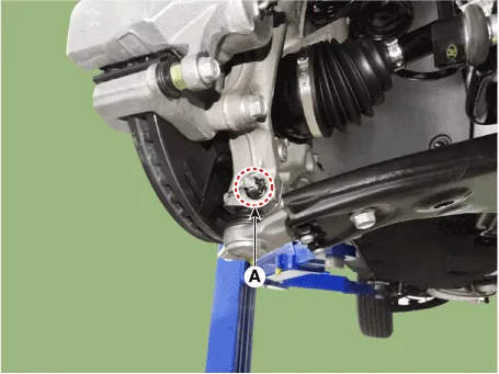
| 4. |
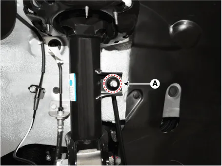
Disconnect the stabilizer link with the front strut assembly after loosening
the nut (A).
|

| 5. |
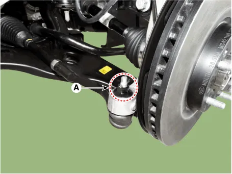
Remove the tie rod end ball joint.
|
| 6. |
Remove the split pin and nut (A).
|
| 7. |
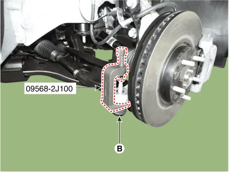
Remove the lower arm from the knuckle by using the SST (09568-4R100).
|

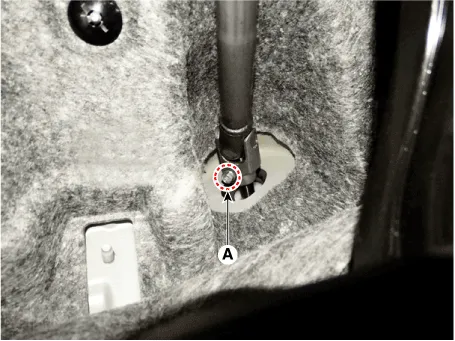
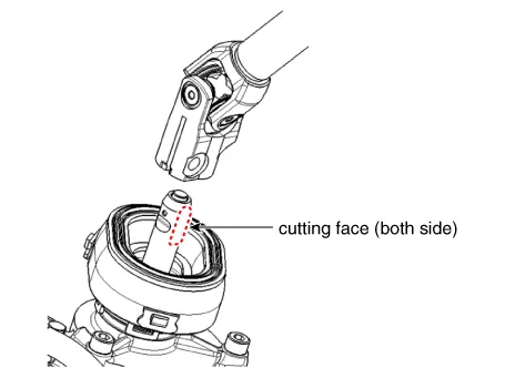
| 8. |
Loosen the bolt (A) and then disconnect the universal joint assembly
from the pinion of the steering gear box.
|

| 9. |
Remove the under cover.
(Refer to Engine Mechanical System - "Engine Room Under Cover")
|
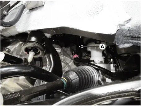
| 10. |
Disconnect the R-MDPS main connector (A). [R-MDPS Type only]
|
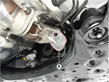
| 11. |
Remove the muffler rubber hanger (A).
|
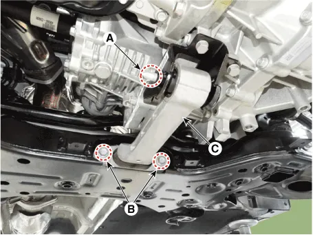
| 12. |
Remove the roll rod bracket (C) by loosening the bolt (A), (B).
|
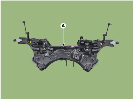
| 13. |
Remove the subframe by loosening the mounting bolts and nuts.
|


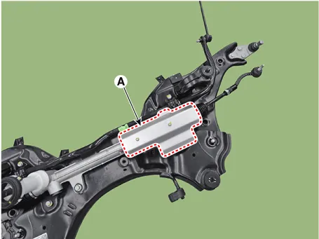
| 14. |
Remove the heated protector (A).
[C-MDPS]
[R-MDPS]
|
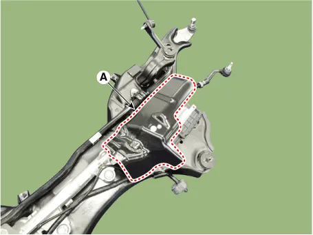
| 15. |
Remove the steering gearbox (A) from the front sub frame by loosening
the mounting bolts.
[C-MDPS]
[R-MDPS]
|
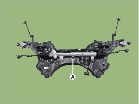
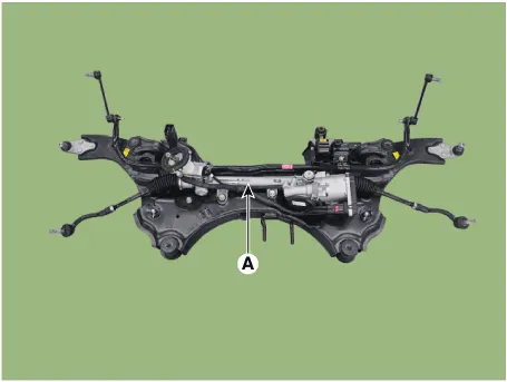
| 16. |
Loosen the mounting bolts and then remove the stabilizer bar (A).
|
| Inspection |
| 1. |
Check the bushing for wear and deterioration.
|
| 2. |
Check the front stabilizer bar for deformation.
|
| 3. |
Check the front stabilizer link ball joint for damage.
|
| Installation |
| 1. |
Install in the reverse order of removal.
|
| 2. |
Check the alignment.
(Refer to Suspension System - "Alingment")
|
Repair procedures Removal 1. Loosen the wheel nuts slightly. Raise the vehicle, and make sure it is securely supported.
Repair procedures Removal 1. Turn the ignition switch OFF and disconnect the battery negative (-) cable. 2.
Other information:
Hyundai Palisade (LX2) 2020-2026 Service Manual: Special service tools
Special Service Tools Tool Name / Number Illustration Description LKA Compensator (09890-3V100) Used for compensating front view camera unit Tolerance Compensation Plate for Surround View Monitoring (09957-CM100)
Hyundai Palisade (LX2) 2020-2026 Service Manual: Smart Cruise Control (SCC) Switch
Components and components location Components 1. Remote control switch (Audio swtich) 2. Remote control switch (Cruise control switch) Schematic diagrams Circuit Diagram Trip + SCC Repair procedures Removal 1.
Categories
- Manuals Home
- Hyundai Palisade Owners Manual
- Hyundai Palisade Service Manual
- Emergency liftgate safety release
- Body (Interior and Exterior)
- General Tightening Torque Table
- New on site
- Most important about car
