Hyundai Palisade (LX2): Driveshaft Assembly / Front Driveshaft
Hyundai Palisade (LX2) 2020-2026 Service Manual / Driveshaft and axle / Driveshaft Assembly / Front Driveshaft
Components and components location
| Components |
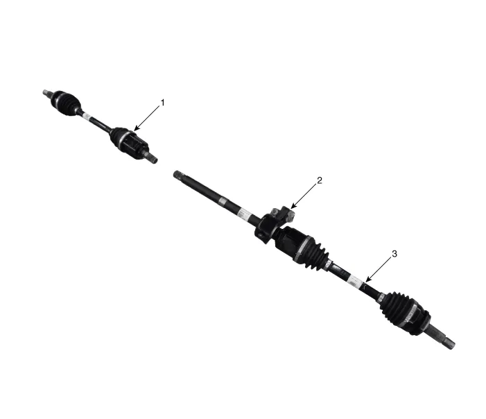
| 1. Front driveshaft (LH) 2. Inner shaft bearing bracket |
3. Front driveshaft (RH) |
Components and components location Components [LH] 1. BJ assembly 2. BJ circlip 3. BJ boot band 4.
Other information:
Hyundai Palisade (LX2) 2020-2026 Service Manual: Repair procedures
Replacement 1. Disconnect the negative (-) battery terminal. 2. Remove the luggage side trim (Refer to Body - "Luggage Side Trim ") 3. Separate the rear mode actuator connector (A), loosen the mounting screws and remove the rear mode ac
Hyundai Palisade (LX2) 2020-2026 Service Manual: Heater & A/C Control Unit (Rear)
Components and components location Component Connector Pin Function Connector PIN No Pin Function Connector PIN No Pin Function A 1 Battery A 17 IGN2 2
Categories
- Manuals Home
- Hyundai Palisade Owners Manual
- Hyundai Palisade Service Manual
- Rain Sensor
- Components and components location
- Electrochromatic Mirror (ECM) with homelink system
- New on site
- Most important about car

Copyright © 2026 www.hpalisadelx.com - 0.0119