Hyundai Palisade (LX2): Indicators And Gauges / Description and operation
| Description |
|
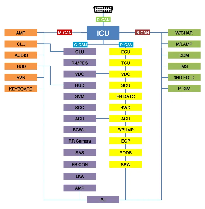
Abbreviation |
Explanation |
|
IBU |
Interated Body Control Unit |
|
DDM |
Driver Door Module |
|
PTGM |
Power Tail Gate Module |
|
ICU |
Interated Control Unit |
|
ECU |
Engine Control Unit |
|
CLU |
Cluster |
|
MDPS |
Moter Driven Power Steering |
|
SVM |
Sorround View Monitor |
|
ACU |
Airbag Control Unit |
|
VDC |
Vehicle Dynamic Control |
|
SCC |
Smart Cruise Control |
|
LKA |
Lane Keeping Assist |
|
BCW |
Blind-Spot Collision Warning |
|
SAS |
Steering Angle Sensor |
|
HUD |
Head up Display |
|
TCU |
Transmission Control Unit |
|
FR DATC |
Dual Automatic Temp Control |
|
4WD |
Four Wheel Drive |
|
F/PUMP |
Fuel Pump Control Module |
|
POCS |
Passenger Occupant Classification System |
|
IMS |
Integrated Memory System |
|
AMP |
Amplifier |
|
AVN |
Head Unit (Audio / AVN) |
|
HUD |
Head Up Display |
|
RR CAMERA |
Rrar View Camera |
|
FR CON |
Front Console Switch |
|
EOP |
Electric Oil Pump |
|
SBW |
Shift BY Wire |
|
W/CHAR |
Wireless Power Chager |
|
FR M/LP |
Front Mood Lamp |
|
3ND FOLD |
3ND Seat Folding Control Unit |
|
AUDIO |
Audio unit |
|
KEY BOARD |
Center Fascia Keyboard |
Components 3.5 Inch MONO LCD 7 Inch TFT LCD Connector Pin Information No Connector A No Connector B 1 Ground 21 Trip switch (-) 2 Illumination (-) 22 Trip switch 1 (+) 3 Rheostat switch (Down)_Input 23 Trip switch 2 (+) 4 Rheostat switch (Up)_Input 24 Active ECO_input switch/ R switch(M/T)_input 5 Dentent 25 Driver mode switch/ N switch(M/T)_input 6 - 26 Speaker1 (+)_Output 7 - 27 Speaker1 (-)_Output 8 - 28 - 9 - 29 B-CAN (Low) 10 - 30 B-CAN (High) 11 - 31 Engine Run State_Output 12 Vehicle speed_Output 32 C-CAN (High) 13 Alternator_Input 33 C-CAN (Low) 14 Fuel sender (+)_Input 34 Temperature_Input 15 - 35 - 16 Fuel sender (-)_Input 36 Steering wheel heater indicator 17 Water separate_Input 37 Ground 18 Airbag (+)_Input 38 - 19 Oil press switch (-)_Input 39 IGN 1 20 - 40 Battery (+)
Removal 1. Disconnect the negative (-) battery terminal. 2. Remove the cluster fascia panel (A).
Other information:
Hyundai Palisade (LX2) 2020-2026 Service Manual: Repair procedures
Variant Coding When you need variant coding: – Replace Front View Camera with a new one ※ EOL Variant Coding and calibration required for new replacement Front View Camera Variant Coding
Hyundai Palisade (LX2) 2020-2026 Service Manual: Smart Cruise Control (SCC) Switch
Components and components location Components 1. Remote control switch (Audio swtich) 2. Remote control switch (Cruise control switch) Schematic diagrams Circuit Diagram Trip + SCC Repair procedures Removal 1.
Categories
- Manuals Home
- Hyundai Palisade Owners Manual
- Hyundai Palisade Service Manual
- Automatic Transaxle System (A8LF1)
- PTG Spindle
- Emergency liftgate safety release
- New on site
- Most important about car
