Hyundai Palisade (LX2): Parking Brake System / Components and components location
| Components |
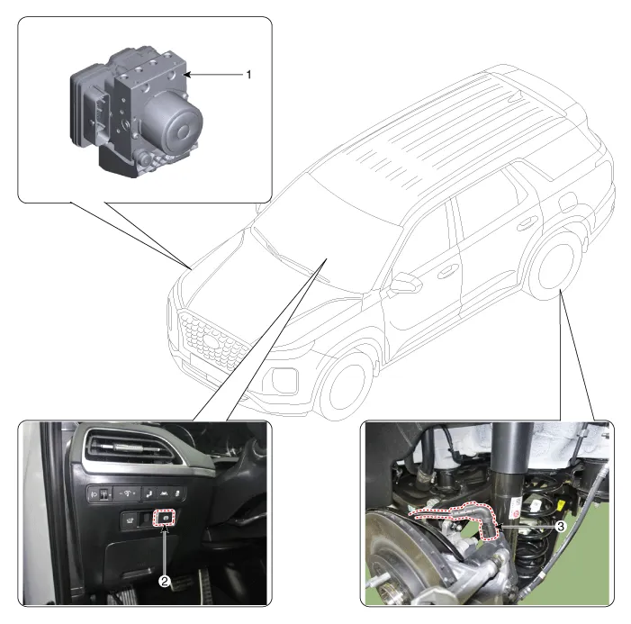
| 1. ESP Control Module (HECU) 2. EPB switch |
3. Electronic Parking Brake (EPB)
actuator |
Description The electronic parking brake (EPB) is different from existing parking systems which operated with the brake pedal or the lever type.
Circuit Diagram Terminal Function Pin No Fuction Pin No Fuction 6 Electrical parking brake signal 1 2 Rear right EPB motor power 7 Electrical parking brake signal 2 3 Rear right EPB motor ground 8 Electrical parking brake signal 3 12 Rear left EPB motor ground 9 Electrical parking brake signal 4 13 Rear left EPB motor power
Other information:
Hyundai Palisade (LX2) 2020-2026 Service Manual: Rear Evaporator Core
Repair procedures Replacement 1. Remove the rear heater & A/C unit. (Refer to Rear Heater - "Rear Heater Unit") 2. Loosen the mounting screws, remove the rear heater & A/C unit cover (A) and evaporator core (B).
Hyundai Palisade (LX2) 2020-2026 Service Manual: Description and operation
Description Rear view camera will activate when the backup light is ON with the ignition switch ON and the shift lever in the R position. This system is a supplemental system that shows behind the vehicle through the AV monitor or the ECM (Reverse Display Room Mirror) mirror while backing-up.
Categories
- Manuals Home
- Hyundai Palisade Owners Manual
- Hyundai Palisade Service Manual
- Lift and Support Points
- Removing and Storing the Spare Tire
- Emission Control System
- New on site
- Most important about car
