Hyundai Palisade (LX2): Audio / Antenna
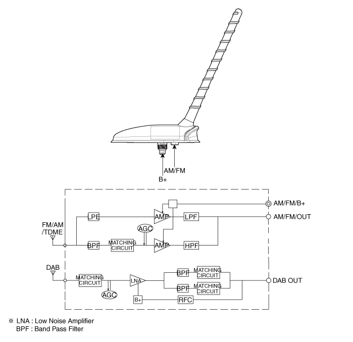
Components and components location
| Components |
Repair procedures
| Removal |
| 1. |
Remove the roof trim assembly.
(Refer to Body - "Roof Trim Assembly")
|
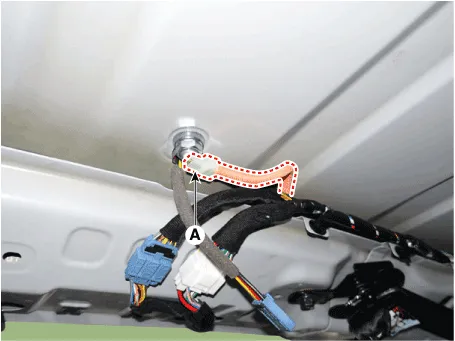
| 2. |
Disconnect the antenna connector (A).
|
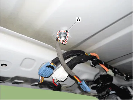
| 3. |
Loosen the mounting nut (A) and then remove the roof antenna.
|
| Installation |
| 1. |
Connect the roof antenna connectors and install the roof antenna.
|
| 2. |
Install the roof trim assembly.
|

Repair procedures Inspection 1. Troubleshooting for Speaker (1) Basic inspection of speaker Inspect the sound from speaker after verifying that the speaker mounting screws is removed and the wiring connector is connected precisely to remove vibration transmitted from body trims and surrounding parts.
Components and components location Components 1. Remote control switch (LH : Audio + Voice) 2. Remote control switch (RH : Trip + Cruise) Schematic diagrams Circuit Diagram [Audio / Bluetooth / Voice] [Trip + Cruise] [Trip + Cruise + Smart cruise] Repair procedures Inspection 1.
Other information:
Hyundai Palisade (LX2) 2020-2026 Service Manual: Description and operating principle
Description and Operation Wireless Power Charger System During ACC or IG ON, battery voltage is supplied to the wireless power charger system to transmit an output of 5 W to mobile phone. Mobile phones certified with the wireless charging standard WPC (Qi 1.
Hyundai Palisade (LX2) 2020-2026 Service Manual: Blower Motor
Repair procedures Inspection 1. Connect the battery voltage and check the blower motor rotation. 2. If the blower motor does not operate well, substitute with a known-good blower motor and check for proper operation.
Categories
- Manuals Home
- Hyundai Palisade Owners Manual
- Hyundai Palisade Service Manual
- Troubleshooting
- Removing and Storing the Spare Tire
- Emergency liftgate safety release
- New on site
- Most important about car
