Hyundai Palisade (LX2): Wireless Power Charger System / Wireless Power Charging Unit
Components and positions
| Components |
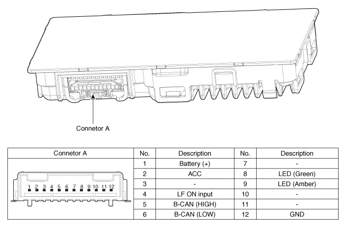
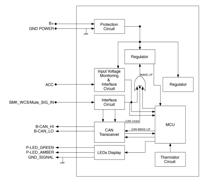
Circuit diagram
| Circuit Diagram |
Repair procedures
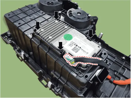
| Removal |
Handling wireless charging system parts by wet hands may cause electric
shock.
|

| 1. |
Disconnect the negative (-) battery terminal.
|
| 2. |
Remove the floor console cover assembly.
(Refer to Body - "Floor Console Assembly")
|
| 3. |
Remove the wireless power charger unit after disconnecting the connector.
|
| Installation |
| 1. |
Connect the wireless power charging unit connectors.
|
| 2. |
Install the wireless power charging unit.
|
| 3. |
Install the floor console assembly.
|
| 4. |
Connect the negative (-) battery terminal.
|
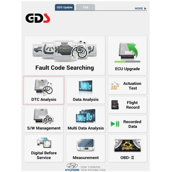
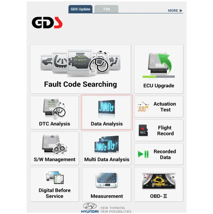
| [Diagnosis With KDS/Diagnostic tool] |
| 1. |
In the body electrical system, failure can be quickly diagnosed by using
the vehicle diagnostic system (Diagnostic tool).
The diagnostic system(Diagnostic tool) provides the following information.
|
| 2. |
If diagnose the vehicle by Diagnostic tool, select "DTC Analysis" and
"Vehicle".
|
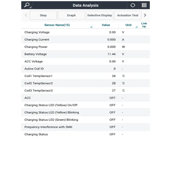
| 3. |
If check current status, select the "Data Analysis" .
|
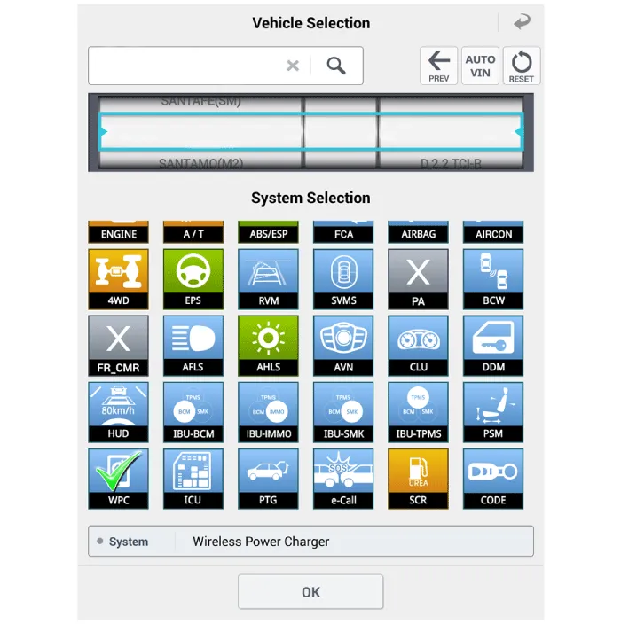
| 4. |
Select the 'WPC' to search the current state of the input/output data.
|
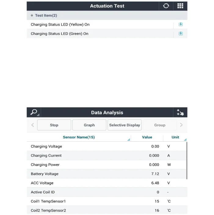
| 5. |
To forcibly actuate the input value of the module to be checked, select
option 'Actuation Test'.
|
Description and Operation Wireless Power Charger System During ACC or IG ON, battery voltage is supplied to the wireless power charger system to transmit an output of 5 W to mobile phone.
Components and positions Components Repair procedures Removal Handling wireless charging system parts by wet hands may cause electric shock.
Other information:
Hyundai Palisade (LX2) 2020-2026 Service Manual: Cluster Ionizer
Description and operation Description The cluster ionizer makes disinfection and decomposition of bad smell from the air-conditioner or inflow air. And it cleans the inside air of a vehicle. When the ignition switch is ON, the ionizer runs "CLEAN" mode and then "ION" mode, switching between both modes.
Hyundai Palisade (LX2) 2020-2026 Service Manual: Description and operation
Description Rear view camera will activate when the backup light is ON with the ignition switch ON and the shift lever in the R position. This system is a supplemental system that shows behind the vehicle through the AV monitor or the ECM (Reverse Display Room Mirror) mirror while backing-up.
Categories
- Manuals Home
- Hyundai Palisade Owners Manual
- Hyundai Palisade Service Manual
- Automatic Transaxle System (A8LF1)
- Cylinder Head
- Removing and Storing the Spare Tire
- New on site
- Most important about car
