Hyundai Palisade (LX2): Hydraulic System / SS-A Solenoid Valve (SS-A_ON/OFF)
Description and operation
| • |
When TCM supplies variable current to solenoid valve, the solenoid valve
operates and controls the speed range.
|
| • |
SS-A solenoid valve is ON/OFF type.

|
Components and components location

1. 28 Brake control solenoid
valve (28/B_VFS)
2. 46 Clutch control solenoid valve (46/C_VFS)
3. 37R Clutch control solenoid valve (37R/C_VFS)
4. UD Clutch control solenoid valve (UD/C_VFS)
|
5. OD Clutch
& LR Brake control solenoid valve (OD/C & LR/B_VFS)
6. SS-A solenoid valve (SS-A_ON/OFF)
7. Torque converter control solenoid valve (T/CON_VFS)
8. Line pressure control solenoid valve (LINE_VFS)
|
Specifications
Clutch & Brake Control VFS
â–· Control type : ON/OFF
Item
|
Specification
|
Control pressure (kpa (kgf/cm, psi))
|
0 - 490.33
(0 - 5, 0 - 71.12)
|
Control voltage (V)
|
9 - 16
|
Internal resistance (Ω)
|
10 - 11
|
â–· Operation of the solenoid valve
Division
|
Solenoid Valve
|
Clutch
|
Brake
|
SS-A
|
OD/C
|
LR/B
|
P
|
â—Ź
|
|
â—Ź
|
R
|
â—Ź
|
|
â—Ź
|
N
|
â—Ź
|
|
â—Ź
|
1
|
â—Ź
|
|
â—Ź
|
2
|
|
|
|
3
|
|
|
|
4
|
|
|
|
5
|
|
â—Ź
|
|
6
|
|
â—Ź
|
|
7
|
|
â—Ź
|
|
8
|
|
â—Ź
|
|
Remark
|
â—Ź : Connected
|
â—Ź: Operation
|
â—Ž : Variable connected
|
Schematic diagrams

Repair procedures
| • |
Refer to the DTC manual for the check procedure.
|
|
| • |
Be careful not to damage the parts located under the vehicle
(floor under cover, fuel filter, fuel tank and canister) when
raising the vehicle using the lift.
(Refer to General Information - "Lift and Support Points")
|
| • |
When the solenoid valve Diagnostic Trouble Codes (DTC) is on,
perform the following procedure to replace it.
|
| • |
Automatic transaxle is composed of delicate components. Be careful
not to cause any damage on the component in the course of assembly
and disassembly.
|
| • |
Maintain clean condition so that foreign substance does not
get into the automatic transaxle.
|
| • |
Use a coated apron, latex gloves, and stainless tray to prevent
foreign substance from getting into the transaxle.
|
| • |
Automatic transaxle fluid (ATF) can be reused. Collect it using
a clean 10-liter beaker.
|
|
| 1. |
Turn ignition switch OFF and disconnect the negative (-) battery cable.
|
| 2. |
Remove the battery and battery tray.
(Refer to Engine Electrical System - "Battery")
|
| 3. |
Remove the air duct and air cleaner assembly.
(Refer to Engine Mechanical System - "Air Cleaner")
|
| 4. |
Remove the under cover.
(Refer to Engine Mechanical System - "Engine Room Under Cover")
|
| 5. |
Drain the coolant.(If equipped ATF warmer)
(Refer to Cooling System - "Coolant")
|
| 6. |
Loosen the drain plug (A) and reinstall the drain plug after draining
ATF totally.
|
Tightening torque :
33.3 - 43.1 N.m (3.4 - 4.4 kgf.m, 24.6 - 31.8 lb-ft)
|

| •
|
Replace the gasket before reinstalling the drain plug.
|
|
|
| 7. |
Loosen the bolts (A) and then removing the wiring bracket.
|
Tightening torque :
9.8 - 11.8 N.m (1.0 - 1.2 kgf.m, 7.2 - 8.7 lb-ft)
|

|
| 8. |
Loosen the bolts (A) and then removing the battery wiring bracket.
|
Tightening torque :
9.8 - 11.8 N.m (1.0 - 1.2 kgf.m, 7.2 - 8.7 lb-ft)
|

|
| 9. |
Remove the ATF cooling hose (A).

| •
|
Carefully install the clamp not to damage the hose.
|
| •
|
Install the clamp in a correct direction not to be interfered
with other parts.
|
| •
|
After the installation, start the engine and then check
if there are any leakages from the hose.
|
|
|
| 10. |
Loosen the upper bolts (A) of the valve body cover.
|
Tightening torque :
11.8 - 13.7 N.m (1.2 - 1.4 kgf.m, 8.7 - 10.1 lb-ft)
|

|
| 11. |
Loosen the bolts and then removing the valve body cover (A).
|
Tightening torque :
11.8 - 13.7 N.m (1.2 - 1.4 kgf.m, 8.7 - 10.1 lb-ft)
|
| •
|
Be careful when removing the valve body cover because
the remaining ATF remains in the valve body cover.
|
|

| •
|
Replace the gasket (A) before reinstalling the valve
body cover.
|
| •
|
After the installation, start the engine and then check
if there are any leakages from the valve body cover.

|
|
|
| 12. |
Loosen the bolts and then removing the main harness (A).
|
Tightening torque :
9.8 - 11.8 N.m (1.0 - 1.2 kgf·m, 7.2 - 8.7 lb-ft)
|

|
| 13. |
Loosen the support bracket mounting bolts (A).
|
Tightening torque :
9.8 - 11.8 N.m (1.0 - 1.2 kgf·m, 7.2 - 8.7 lb-ft)
|

|
| 14. |
Remove the support bracket (A).

|
| 15. |
Remove the SS-A Solenoid Valve (A).
|
Tightening torque :
9.8 - 11.8 N.m (1.0 - 1.2 kgf·m, 7.2 - 8.7 lb-ft)
|
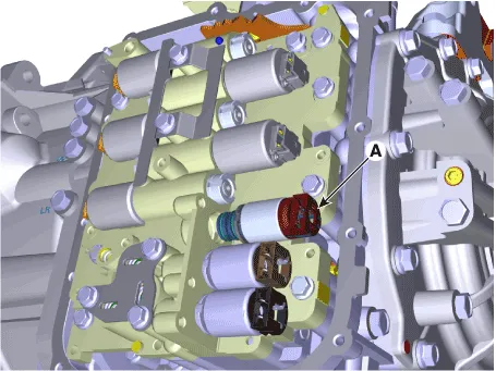
| •
|
When installing, apply the ATF oil or petroleum jelly
to the O-rings (A) to prevent damage.

|
|
|
| 1. |
To install, reverse the removal procedure.
|
| 2. |
Inject the automatic transaxle oil and inspect the oil level.
(Refer to Automatic Transaxle System - "Automatic Transaxle Fluid")
|
| 3. |
Clear the diagnostic trouble codes (DTC) using the diagnostic tool.
| •
|
Even though disconnecting the battery negative terminal,
the DTCs will not be cleared. So, be sure to clear the
DTCs using the diagnostic tool.
|
|
|
| 4. |
In order to prevent start delay and gear shift shock during acceleration
and start, perform TCM learning after replacing the solenoid valve.
(Automatic Transaxle Control System - "Repair Procedures")
| •
|
After ATF level check or exchange, be sure to remove
residual ATF on transaxle case.
(Be especially sure to remove residual ATF between automatic
transaxle case and valve body cover)
|
|
|
Description and operation
Description
•
When TCM supplies variable current to solenoid valve, hydraulic pressure
is controlled indirectly by solenoid valve.
Other information:
Instructions (R-134a)
When Handling Refrigerant
1.
R-134a liquid refrigerant is highly volatile. A drop on the skin of
your hand could result in localized frostbite. When handling the refrigerant,
be sure to wear gloves.
Components and components location
Components Location
1. Blower unit assembly
Components
1. Intake seal
2. Intake upper case
3. Intake actuator
4. Intake door
5.


