Hyundai Palisade (LX2): Windshield Wiper/Washer / Windshield Wiper-Washer Switch
Hyundai Palisade (LX2) 2020-2026 Service Manual / Body Electrical System / Windshield Wiper/Washer / Windshield Wiper-Washer Switch
Repair procedures
| Removal |
| 1. |
Disconnect the negative (-) battery terminal.
|
| 2. |
Remove the steering wheel.
(Refer to Steering System - "Steering Wheel")
|
| 3. |
Remove the steering columm shround.
(Refer to Steering System - "Steering Columm Shround panel")
|
| 4. |
Remove the clock spring.
(Refer to Restraint - "Driver Airbag(DAB) and Clock Spring")
|
| 5. |
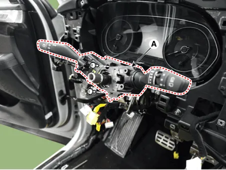
Remove the multifunction connector (A).
|

| 6. |
Remove the multifunction switch (A) after loosening the mounting screws
(2EA).
|
| Installation |
| 1. |
Install the multifunction switch after connecting the connector.
|
| 2. |
Install the clock spring and steering.
|
| 3. |
Install the upper and lower shroud.
|
| 4. |
Install the steering wheel.
|
| Inspection |
| 1. |
Check for continuity between the terminals in each switch position as
shown below.
|

Inspection (With Diagnostic tool)
| 1. |
In the body electrical system, failure can be quickly diagnosed by using
the vehicle diagnostic system (Diagnostic tool).
The diagnostic system (Diagnostic tool) provides the following information.
|
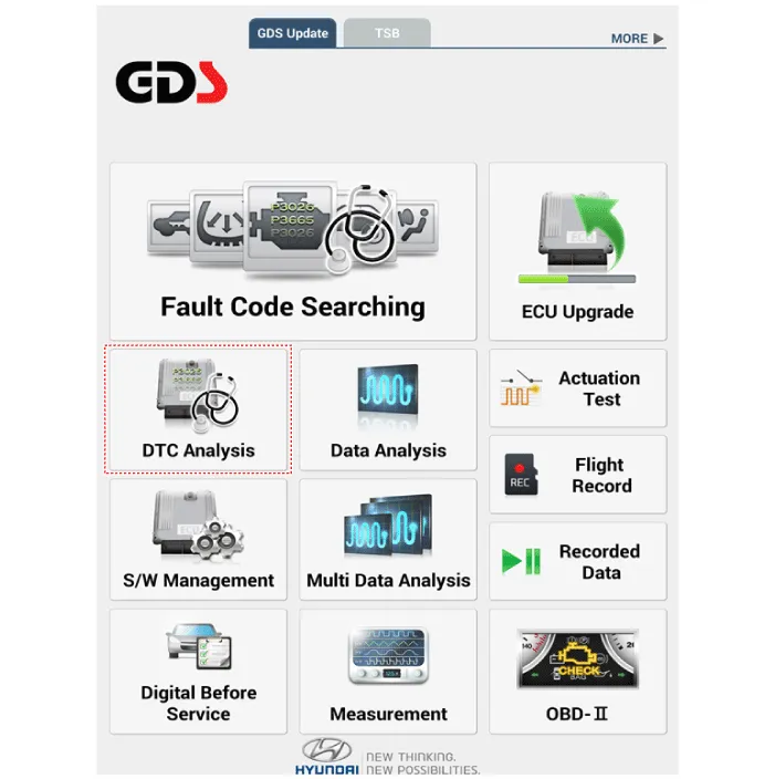
| 2. |
If diagnose the vehicle by Diagnostic tool, select "DTC Analysis" and
"Vehicle".
|
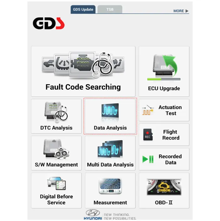
| 3. |
If check current status, select the "Data Analysis" .
|
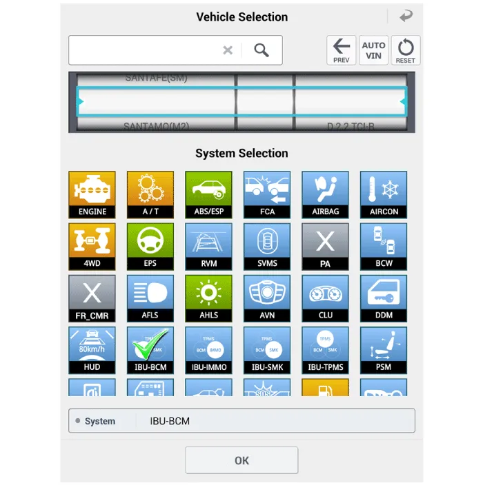
| 4. |
Select the 'IBU_BCM' to search the current state of the input/output
data.
|

Component Location 1. Windshield wiper arm & blade 2. Wiper & washer switch 3. Windshield washer hose 4. Windshield wiper motor & linkage 5.
Components and components location Component Location 1. Cap 2. Nut 3. Wiper arm & blade 4. Cowl top cover 5.
Other information:
Hyundai Palisade (LX2) 2020-2026 Service Manual: Specification
Hyundai Palisade (LX2) 2020-2026 Service Manual: A/C Pressure Transducer
Description and operation Description The A/C Pressure Transducer (APT) converts the pressure value of high pressure line into voltage value after measuring it. By converted voltage value, engine ECU controls the cooling fan by operating it high speed or low speed.
Categories
- Manuals Home
- Hyundai Palisade Owners Manual
- Hyundai Palisade Service Manual
- Scheduled maintenance services
- Power Outlet
- Rain Sensor
- New on site
- Most important about car

Copyright © 2026 www.hpalisadelx.com - 0.0172