Hyundai Palisade (LX2): Keyless Entry And Burglar Alarm / Repair procedures
Hyundai Palisade (LX2) 2020-2026 Service Manual / Body Electrical System / Keyless Entry And Burglar Alarm / Repair procedures
| Inspection |
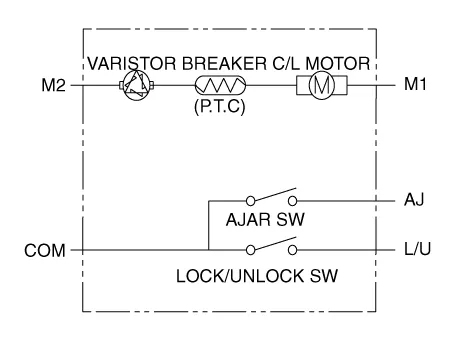
Front Door Lock Module Inspection
| 1. |
Remove the front door trim.
(Refer to Body - "Front Door Trim")
|
| 2. |
Remove the front door module.
(Refer to Body - "Front Door Module")
|
| 3. |
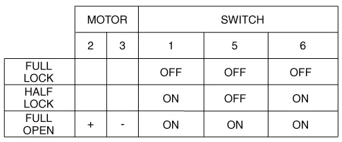
Disconnect the connectors from the actuator.
|
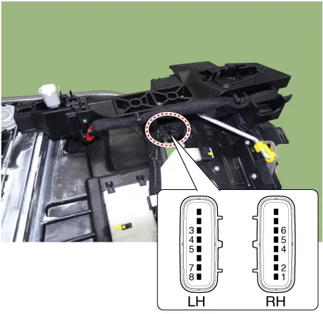
| 4. |
Check actuator operation by connecting power and ground according to
the table.
|
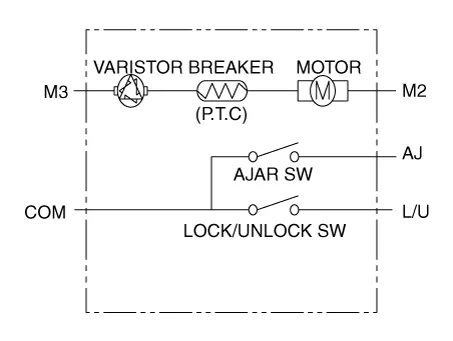

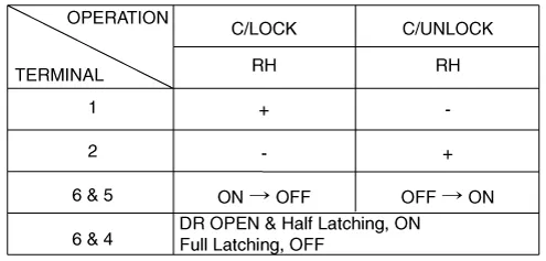
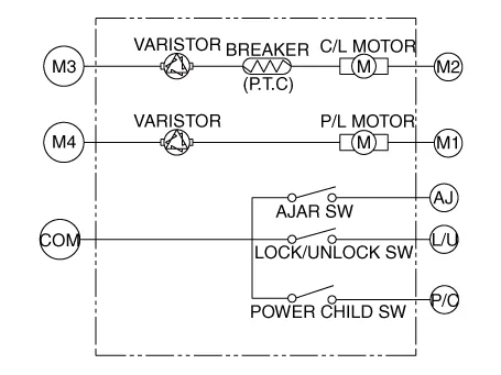
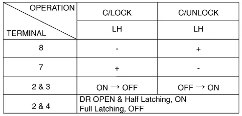
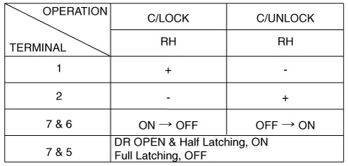
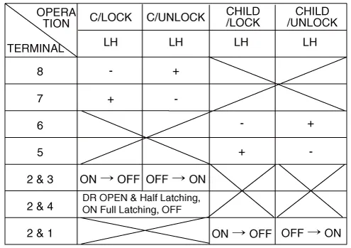
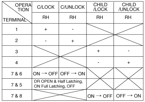
Rear Door Lock Module Inspection
| 1. |
Remove the rear door trim.
(Refer to Body - "Rear Door Trim")
|
| 2. |
Remove the rear door module.
(Refer to Body - "Rear Door Module")
|
| 3. |
Disconnect the connectors from the actuator.
|
| 4. |
Check actuator operation by connecting power and ground according to
the table.
[Central Lock]
[Power Child Lock]
[Central Lock]
[Power Child Lock]
|
|||||||||||||||||||||||||||||||||||||||||||||||||
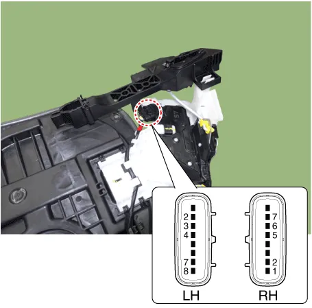
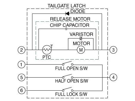
Tailgate Lock Module Inspection
| 1. |
Remove the tailgate trim.
(Refer to Body - "Tailgate Trim")
|
| 2. |
Disconnect the 4P connector from the actuator.
|
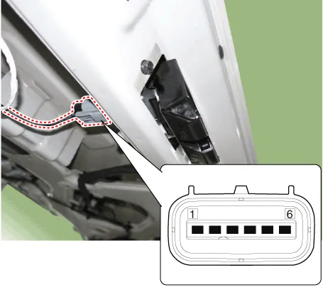
| 3. |
Check actuator operation by connecting power and ground according to
the table.
|
Hood Switch
| 1. |
Disconnect the connector and bolts from the hood switch.
|
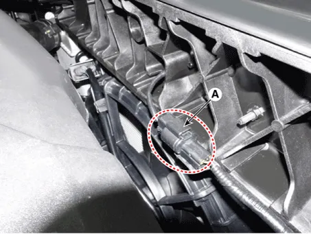
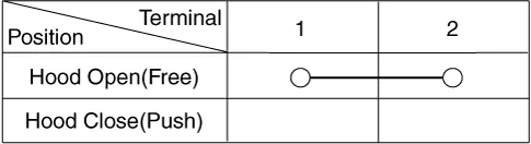
| 2. |
Check for continuity between the terminals and ground according to the
table.
|
Description Burglar Alarm State [B/A State] B/A State Description DISARM 1) In "DISARM" state, no vehicle start inhibition.
Other information:
Hyundai Palisade (LX2) 2020-2026 Service Manual: Temperature Control Actuator
Description and operation Description The heater unit includes mode control actuator and temperature control actuator. The temperature control actuator is located at the heater unit. It regulates the temperature by the procedure as follows.
Hyundai Palisade (LX2) 2020-2026 Service Manual: Rear Heater Core
Repair procedures Replacement 1. Remove the rear heater & A/C unit. (Refer to Rear Heater - "Rear Heater Unit") 2. Loosen the mounting screws and remove the rear heater core cover (A).
Categories
- Manuals Home
- Hyundai Palisade Owners Manual
- Hyundai Palisade Service Manual
- Lift and Support Points
- Resetting the Driver's Seat Memory System
- Scheduled maintenance services
- New on site
- Most important about car

Copyright © 2026 www.hpalisadelx.com - 0.0151