Hyundai Palisade (LX2): Brake System / Brake Pad
Repair procedures
| Replacement |
|

Front Brake Pad
| 1. |
Loosen the wheel nuts slightly.
Raise the vehicle, and make sure it is securely supported.
|
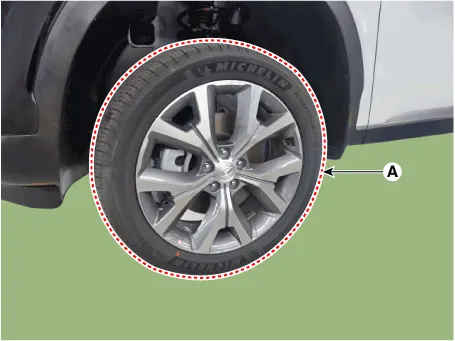
| 2. |
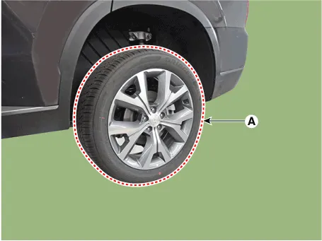
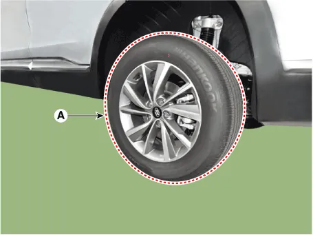
Remove the front wheel and tire (A) from front hub.
|


| 3. |
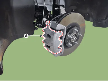
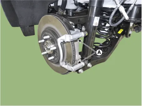
Up the brake caliper body (A) by loosening the guided rod bolt.
|
| 4. |
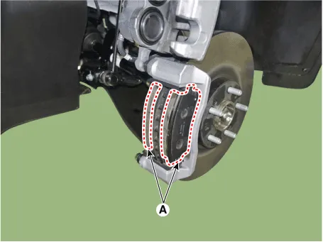
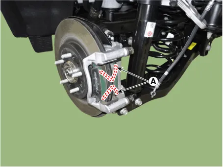
Remove the brake pad (A).
|

| 5. |
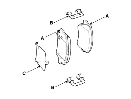
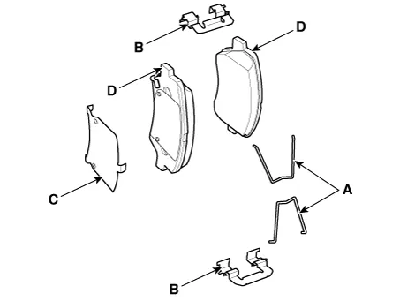
Replace the pad retainer (A) with a new one.
|
| 6. |
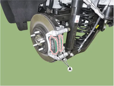
Replace the brake pad (A) with a new one.
|

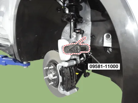
| 7. |
Use a SST (09581-11000) when installing the brake caliper assembly.
|
| 8. |
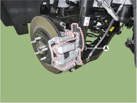
Install the caliper body (A) then tighten the guide rod bolt.
|

| 9. |
Install the front wheel and tire (A).
|
Rear Brake Pad
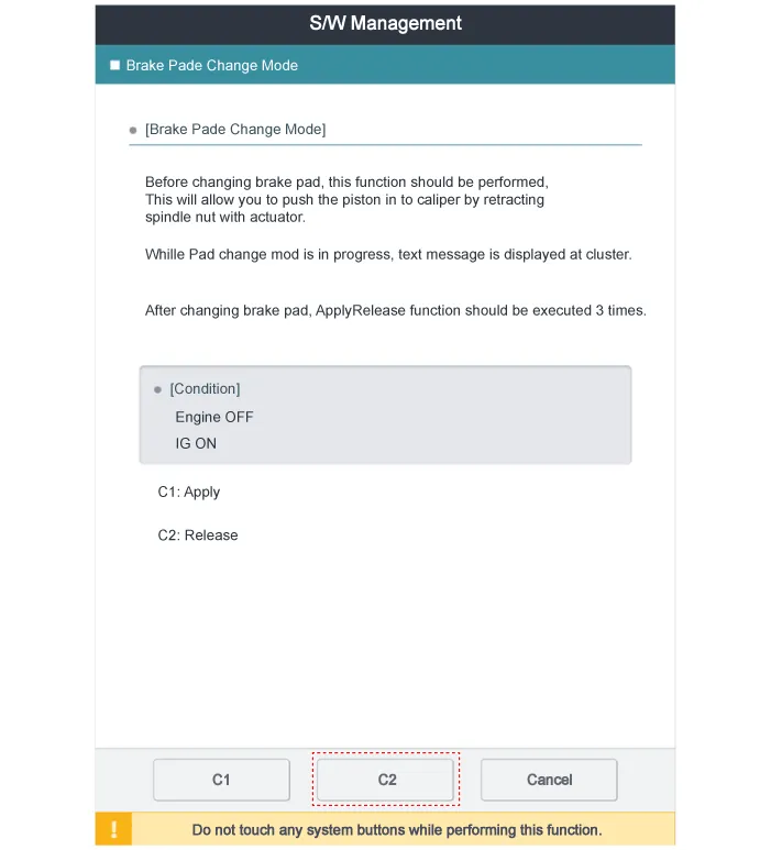
| 1. |
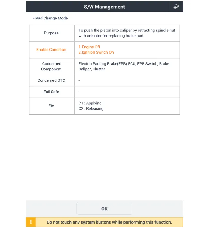
Before removing the rear caliper, perform "Brake Pad Replacement Mode" using
the GDS.
|
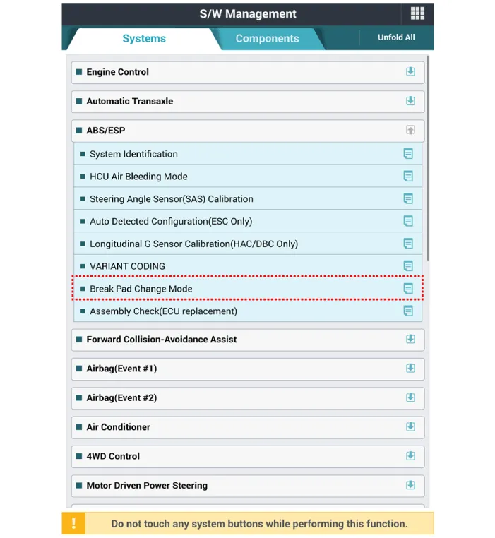

| 2. |
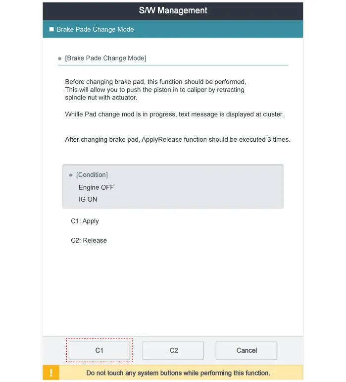
Select C2 (Release) on the screen below.
|
| 3. |
Loosen the wheel nuts slightly.
Raise the vehicle, and make sure it is securely supported.
|
| 4. |
Remove the rear wheel and tire (A) from the rear hub.
|

| 5. |
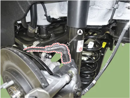
Disconnect the EPB actuator connector (A).
|
| 6. |
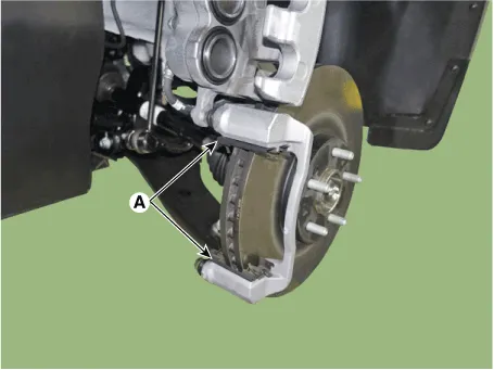
Remove the caliper body (A) after loosening the guide rod bolt.
|

| 7. |
Remove the pad return spring (A).
|
| 8. |
Remove the brake pad (A).
|
| 9. |
Replace the pad retainer (A) with a new one.
|
| 10. |
Replace the brake pad (A) with a new one.
|


| 11. |
Install the pad return spring (A).
|


| 12. |
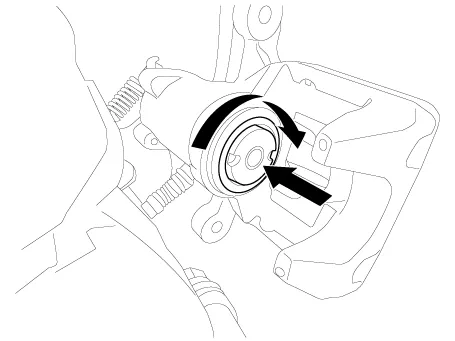
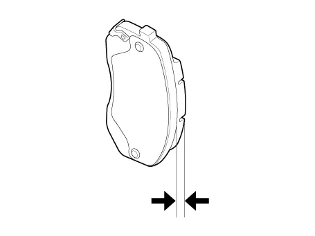
Rotate the caliper piston and push the direction of the arrow.
|
| 13. |
Install the caliper body (A) then tighten the guide rod bolt.
|
| 14. |
Install the rear wheel and tire (A).
|

| 15. |
After replacing the brake pad (EPB applied), perform "Brake Pad Replacement
Mode" using the GDS.
|

| 16. |
Select C1 (Apply) on the screen below.
|

| 17. |
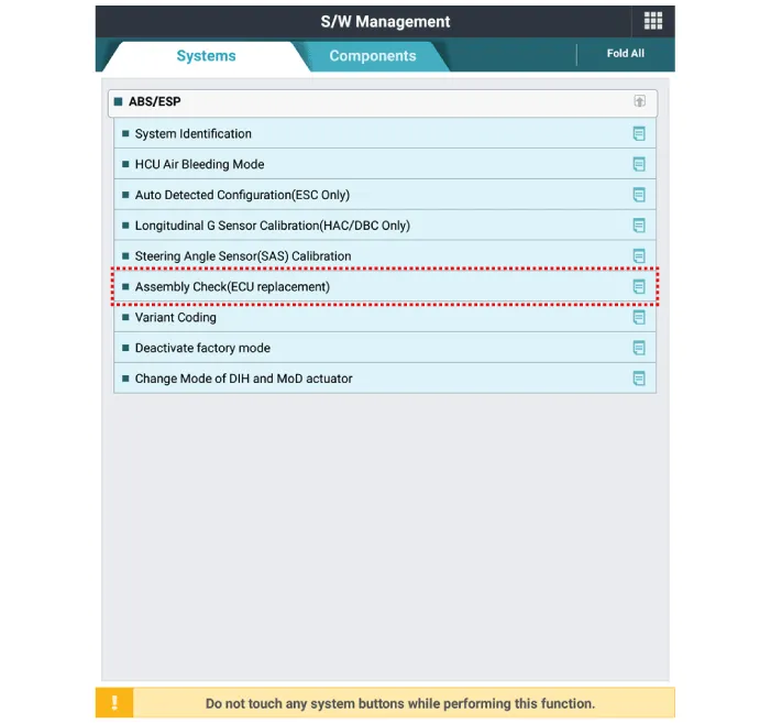
After replacing the brake pad, make sure that the caliper is installed
correctly by performing "Check assembling (ECU replaced)" from the optional
function.
|
| Inspection |
Front Brake Pad Check
| 1. |
Check the pad wear. Measure the pad thickness and replace it, if it
is less than the specified value.
|
| 2. |
Check that grease is applied, to sliding contact points and the pad
and backing metal for damage.
|
Rear Brake Pad Check
| 1. |
Check the pad wear. Measure the pad thickness and replace it, if it
is less than the specified value.
|
| 2. |
Check the damage of pad, backing metal and contamination with grease.
|
Components and components location Components 1. EPB actuator 2. Caliper body 3. Guide rod pin 4. Guide rod boot 5.
Components and components location Components 1. Brake member assembly 2. Stop lamp switch 3. Brake pedal arm assembly 4.
Categories
- Manuals Home
- Hyundai Palisade Owners Manual
- Hyundai Palisade Service Manual
- How to reset the power liftgate
- Body (Interior and Exterior)
- Body Electrical System
- New on site
- Most important about car

Copyright © 2026 www.hpalisadelx.com - 0.0103