
Hyundai Palisade (LX2): Crankcase Emission Control System / Positive Crankcase Ventilation (PCV) Valve
Description and operation
| Operation Principle |

Repair procedures
| Removal |
| 1. |
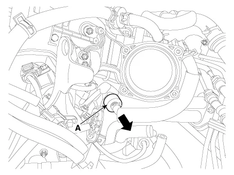
Release the PCV pad.
|
| 2. |
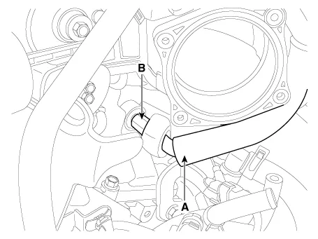
Disconnect the vapor hose (A).
|
| 3. |
Remove the PCV valve (B).
|
| Inspection |
| 1. |
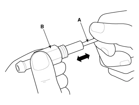
Insert a thin stick (A) into the PCV valve (B) from the threaded side
to check for plunger movement.
|

| Installation |
| 1. |
Install in the reverse order of removal.
|

Inspection 1. After disconnecting the vapor hose from the PCV valve, remove the PCV valve. 2. Reconnect the PCV valve to the vapor hose.
Other information:
Hyundai Palisade (LX2) 2020-2026 Service Manual: Auto Defogging Actuator
Description and operation Description The auto defogging sensor is installed on the front window glass. The sensor judges and sends signal if moisture occurs to blow out wind for defogging. The air conditioner control module receives a signal from the sensor and restrains moisture and eliminates defog by the intake actuato
Hyundai Palisade (LX2) 2020-2026 Service Manual: Description and operation
Description Surround View Monitor (SVM) is the system that allows video monitoring of 360 degrees around the vehicle. The system includes 4 ultra optical camera mounted around the vehicle (front, both sides, rear). The video from these cameras are applied with distortion compensation, time point conversion, and video me
Categories
- Manuals Home
- Hyundai Palisade Owners Manual
- Hyundai Palisade Service Manual
- Rain Sensor
- Identification Numbers
- Scheduled maintenance services
- New on site
- Most important about car
