Hyundai Palisade (LX2): Brake System / Master Cylinder
Components and components location
| Components |
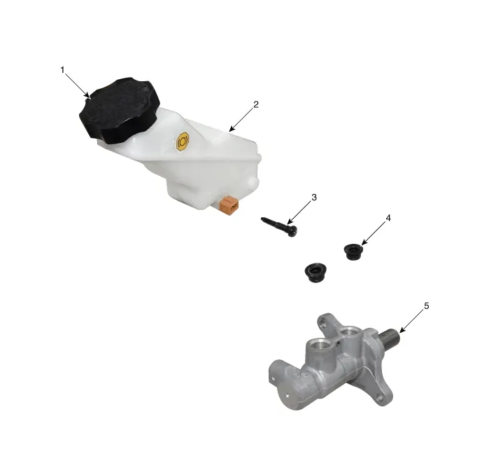
| 1. Reservoir cap 2. Reservoir 3. Reservoir pin |
4. Grommet 5. Master cylinder |
Repair procedures
| Removal |
| 1. |
Turm ignition switch OFF and disconnect the negative (-) battery cable.
|
| 2. |
Remove the air cleaner assembly.
(Refer to Engine Mechanical System - "Air Cleaner")
|
| 3. |
Disconnect the brake fluid level sensor connector (A).
|

| 4. |
Remove the brake fluid from the master cylinder reservoir with a syringe.
|

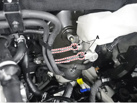
| 5. |
Separate the brake tube (A) from the master cylinder by loosening the
tube flare nut.
|
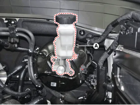
| 6. |
Remove the master cylinder (A) after loosening the master cylinder nuts.
|
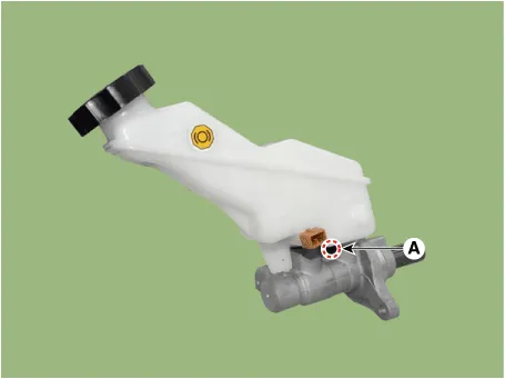
| 7. |
Separate the reservoir from the master cylinder after remove the screw
(A).
|
| Installation |
| 1. |
To install, reverse the removal procedures.
|

| 2. |
After installation, bleed the brake system.
(Refer to Brake System - "Brake System Bleeding")
(Refer to Brake System - "ESP System Bleeding)
|
| 3. |
Check the brake oil leakage and pedal operating condition.
|
Components and components location Components 1. Reservoir cap 2. Reservoir 3. Brake booster 4. Master cylinder 5.
Components and components location Components
Other information:
Hyundai Palisade (LX2) 2020-2026 Service Manual: Rear Temperature Control Actuator
Repair procedures Replacement 1. Disconnect the negative (-) battery terminal. 2. Remove the luggage side trim (Refer to Body - "Luggage Side Trim ") 3. Separate the rear temperature actuator connector (A), loosen the mounting screws a
Hyundai Palisade (LX2) 2020-2026 Service Manual: Troubleshooting
Troubleshooting 1) After replacing H/UNIT, always check that the system operates properly. 2) If the failure persists after replacing the H/UNIT, do not replace the unit.
Categories
- Manuals Home
- Hyundai Palisade Owners Manual
- Hyundai Palisade Service Manual
- Convenient Features of Your Vehicle
- Lift and Support Points
- How to reset the power liftgate
- New on site
- Most important about car
