Hyundai Palisade (LX2): Integrated Body Control Unit (IBU) / Components and components location
| Components (1) |
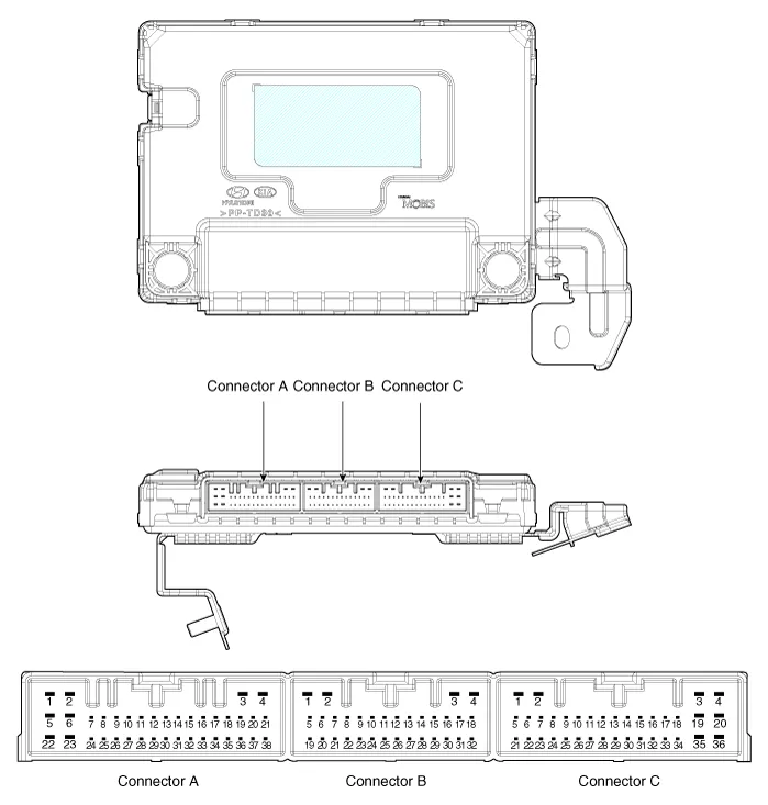
|
No |
Connector A |
Connector B |
Connector C |
|
1 |
- |
GND_ECU |
Front wiper relay (Low)_output |
|
2 |
- |
PDW-F power_output |
ESCL (+)_output |
|
3 |
GND_Power |
ESCL (-)_output |
Start relay_output |
|
4 |
PDW-R_Power_Output |
Front wiper high relay_output |
IGN1 relay_output |
|
5 |
- |
PDW-R WIND_output |
Immobilizer antenna power_output |
|
6 |
Rear washer switch_input |
- |
Immobilizer antenna ground_output |
|
7 |
LIN4 (Rear seat remind) |
- |
- |
|
8 |
P_CAN (Low) |
Rear view switch_input |
Interior1 antenna (+)_output |
|
9 |
P_CAN (High) |
- |
Driver outside handle antenna(+)_output |
|
10 |
- |
Wheel speed sensor_input |
- |
|
11 |
B_CAN (Low) |
- |
Passenger outside handle antenna(+)_output |
|
12 |
B_CAN (High) |
3rd line sheet belt indicator RH_output |
- |
|
13 |
SSB switch_input |
Passenger seat belt indicator_output |
Trunk interior antenna3(+)_output |
|
14 |
Driver handle antenna switch_input |
Rear center seat belt indicator_output |
Immobilizer K-Line |
|
15 |
P position_input (AT) |
- |
Bumper antenna (+)_output |
|
Clutch lock switch_input (MT) |
|||
|
16 |
Fog switch_input |
LF searching_output |
Interior antenna2(+)_output |
|
17 |
Light switch_input |
Auto light sensor signal_input |
IGN2_input |
|
18 |
Front wiper INT volume switch_input |
Auto light sensor power_output |
IGN1_input |
|
19 |
Multifunction switch_input |
ATM solenoid_output |
IGN2 relay_output |
|
20 |
Right side mirror unfolding switch_oupout |
Puddle pocket lamp_output |
Battery_power |
|
21 |
Right side mirror heater_output |
- |
Brake switch_input |
|
22 |
Front washer switch_input |
SSB ring illumination_output |
Start feedback_input |
|
23 |
Front wiper low switch_Input |
piezo buzzer_output |
Security indicator_output |
|
24 |
LIN1 (PDW) |
SSB symbol illumination_output |
Interior1 (-)_output |
|
25 |
LIN2 (Safety ECU) |
- |
Driver outside handle antenna (-)_output |
|
26 |
LIN3 (Rain sensor) |
Wiper power relay_output |
- |
|
27 |
PDW/PDW-R power_input |
Rear seat belt indicator RH_output |
Passenger outside handle antenna (-)_output |
|
28 |
PDW_input |
Rear seat belt indicator LH_output |
ESCL COM |
|
29 |
SSB switch1_input |
3rd line sheet belt indicator LH_output |
Trunk Interior antenna3(-)_output |
|
30 |
ESCL unlock_input |
Rear wiper relay_output |
ESCL Enable_output |
|
31 |
Passenger outside handle switch_input |
Auto light sensor ground_output |
Bumper antenna (-)_output |
|
32 |
PDW switch_input |
Wiper parking switch_input |
Interior antenna2 (-)_output |
|
33 |
Sun roof Status_input |
|
|
|
34 |
Head lamp switch_input |
||
|
35 |
Front wiper switch_input |
||
|
36 |
Rear wiper switch_input |
||
|
37 |
Mirror folding RH_output |
||
|
38 |
Mirror RH VT_output |
Specifications Items Specifications Rated voltage DC -40V Operating voltage DC -40V Operating temperature -40°C to 85°C (-22°F to 185°F) parastic current 4.
Circuit Diagram
Other information:
Hyundai Palisade (LX2) 2020-2026 Service Manual: Repair procedures
Refrigerant System Service Basics (R-134a) Refrigerant Recovery Use only service equipment that is U.L-listed and is certified to meet the requirements of SAE J2210 to remove HFC-134a(R-134a) from the air conditioning system.
Hyundai Palisade (LX2) 2020-2026 Service Manual: Power Mosfet (DATC)
Repair procedures Inspection 1. Turn the ignition switch ON. 2. Manually operate the control switch and measure the voltage of the blower motor. 3. Select the control switch to raise the voltage until high speed.
Categories
- Manuals Home
- Hyundai Palisade Owners Manual
- Hyundai Palisade Service Manual
- Lift and Support Points
- Rear Heater Unit
- Electronic Child Safety Lock System
- New on site
- Most important about car
