
Hyundai Palisade (LX2): Seat Electrical / 2nd Seat Work In System
Components and components location
| Component Location |


Schematic diagrams
| Circuit Diagram |
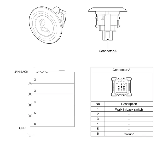
Repair procedures
| Removal |
| 1. |
Remove the rear seat.
(Refer to Body - "Rear Seat Assembly")
|
| 2. |
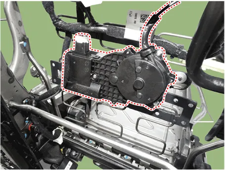
Disconnect the walk in actuator connector and then remove the actuator.
|
| 3. |
Remove the cable (A) and then separate the walk in actuator.
|

| 1. |
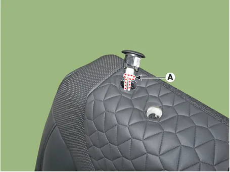
Remove the rear seat walk in switch (A).
|

| 2. |
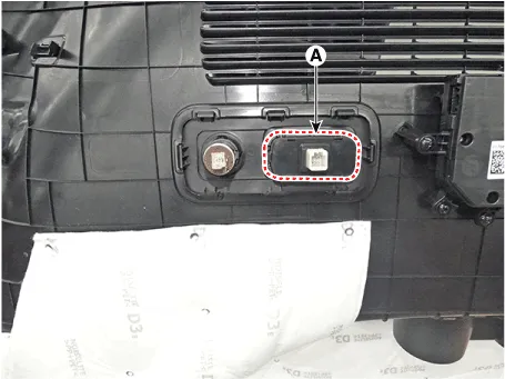
Remove the walk in switch by using a flat-head screwdriver and then
disconnect the walk in switch connector (A).
|
| 1. |
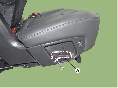
Loosen the screw and then remove the rear slide Knob (A).
|
| 2. |
Loosen the screw and then remove the rear seat slide outer cover (A).
|

| 3. |
Remove the walk in swtich (A) after loosening the connector.
|

| 1. |
Remove the luggage side trim.
(Refer to Body - "Luggage Side Trim")
|
| 2. |
Remove the luggage remote folding switch (A).
|
Components and components location Components (1) Front seat 1. Air ventilation seat blower 2. Air ventilation seat control unit (Passenger only) 3.
Components and components location Components 3rd Seat 1. 3rd right folding motor 2. Folding seat control unit 3.
Other information:
Hyundai Palisade (LX2) 2020-2026 Service Manual: Troubleshooting
Diagnosis with Diagnostic tool 1. In the body electrical system, failure can be quickly diagnosed by using the vehicle diagnostic system (Diagnostic tool). The diagnostic system (Diagnostic tool) provides the following information.
Hyundai Palisade (LX2) 2020-2026 Service Manual: Description and operation
Description • PDW consists of 8 sensors (front : 4 units, rear : 4 units) that are used to detect obstacles and transmit the result in three separate warning levels, the first, second and third to IBU via LIN communication.
Categories
- Manuals Home
- Hyundai Palisade Owners Manual
- Hyundai Palisade Service Manual
- Engine Mechanical System
- Lift and Support Points
- Identification Numbers
- New on site
- Most important about car
