Hyundai Palisade (LX2): Steering wheel / Heated Steering wheel
Hyundai Palisade (LX2) 2020-2026 Service Manual / Steering System / Steering wheel / Heated Steering wheel
Description and operation
| Description |
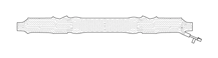
Heated pads to grip the steering grip makes the fever.
Heated pad
Specifications
| Specifications |
|
Item |
Specification |
|
Voltage |
13.5 V |
|
Heated pad resistance |
1.68 Ω ± 10 % |
|
NTC resistance |
10.0 kΩ ± 5 % (25 °C) |
Schematic diagrams
| System Circuit Diagram |


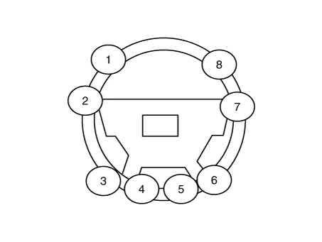
Terminal Function
|
Item |
Pin |
Function |
Wire color |
|
Pad |
A |
HEATER |
Red / Black |
|
B |
GND |
Brown / Black |
|
|
C |
NTC- |
Black |
|
|
D |
NTC+ |
Black |
|
|
Remote control |
A |
GND |
Black |
|
B |
BAT |
Red |
|
|
C |
LED |
Green |
|
|
D |
SWITCH |
White |
Repair procedures
| Inpection |
| 1. |
Measure a resistance of NTC and Heated pad.
|
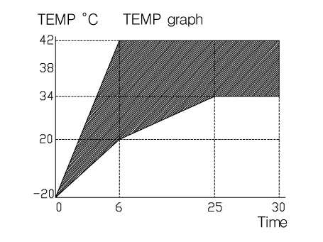
| 2. |
Measure a temperature.
|
Removal 1. Turn the ignition switch OFF and disconnect the battery negative (-) cable. 2. Turn the steering wheel so that the front wheels can face straight ahead.
Other information:
Hyundai Palisade (LX2) 2020-2026 Service Manual: Components and components location
Hyundai Palisade (LX2) 2020-2026 Service Manual: Cruise Control (CC) Switch
Components and components location Components 1. Remote control switch (Audio swtich) 2. Remote control switch (Cruise control switch) Schematic diagrams Circuit Diagram Repair procedures Removal 1.
Categories
- Manuals Home
- Hyundai Palisade Owners Manual
- Hyundai Palisade Service Manual
- PTG Spindle
- How to reset the power liftgate
- Electrochromatic Mirror (ECM) with homelink system
- New on site
- Most important about car

Copyright © 2026 www.hpalisadelx.com - 0.0119