Hyundai Palisade (LX2): Engine Control System / ETC (Electronic Throttle Control) System
Description and operation
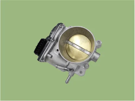
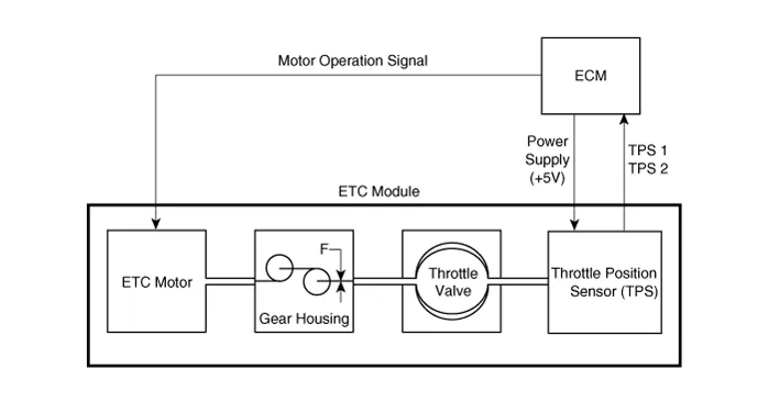
The Electronic Throttle Control (ETC) System consists of a throttle body with
an integrated control motor and throttle position sensor (TPS). Unlike the existing
mechanical throttle system that controls the throttle valve by using wire cable
connected to the accelerator pedal, the ETC system controls the opening and
closing of the throttle valve by the ECM with ETC motor according to the APS
(Accelerator Position Sensor) signal mounted to electronic accelerator pedal
module. The TPS signal is used to provide feedback regarding throttle position
to the ECM. Also, the ETC system has the benefit of implementing cruise control
function without additional external cruise control modules/cables.
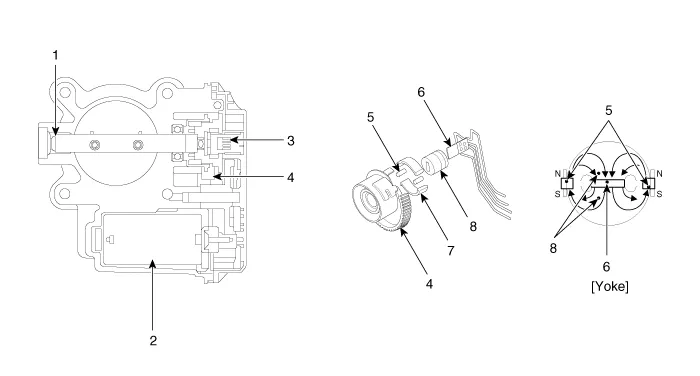
1. Dry bearing
2. DC motor
3. Non-contact hall sensor
4. Gear
|
5. Magnet
6. Hall IC
7. Yoke
8. Stator
|
Specifications
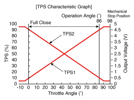
[Throttle Position Sensor (TPS)]
Throttle angle (°)
|
Output Voltage (V) [Vref = 5V]
|
TPS1
|
TPS2
|
0
|
0.5
|
4.5
|
10
|
0.96
|
4.05
|
20
|
1.41
|
3.59
|
30
|
1.87
|
3.14
|
40
|
2.32
|
2.68
|
50
|
2.78
|
2.23
|
60
|
3.23
|
1.77
|
70
|
3.69
|
1.32
|
80
|
4.14
|
0.86
|
90
|
4.60
|
0.41
|
98
|
4.65
|
0.35
|
C.T (0)
|
0.5
|
4.5
|
W.O.T (86)
|
4.41
|
0.59
|
[ETC Motor]
Item
|
Specification
|
Coil Resistance (Ω)
|
0.3 -100 [20°C (68°F)]
|
Troubleshooting
Item
|
Fail-Safe
|
ETC Motor
|
Throttle valve stuck at 7°
|
TPS
|
TPS 1 fault
|
ECM looks at TPS2
|
TPS 2 fault
|
ECM looks at TPS1
|
TPS 1, 2 fault
|
Throttle valve stuck at 7°
|
APS
|
APS 1 fault
|
ECM looks at APS 2
|
APS 2 fault
|
ECM looks at APS 1
|
APS 1, 2 fault
|
Engine idle state
|
| • |
When throttle value is stuck at 7°, engine speed will be limited
to below 1,500 rpm and vehicle speed to maximum of 40 - 50 km/h
(25 - 31 mph).
|
|
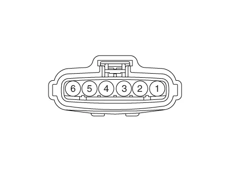
Schematic diagrams
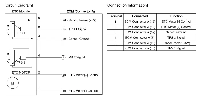
Harness Connector
Repair procedures
If idle rpm is unstable or engine stops, check the ETC module operation with
diagnostic tool diagnostic tool.
And if necessary, clean carbon in the throttle body.
| 1. |
Connect the diagnostic tool to the Data Link Connector (DLC).
|
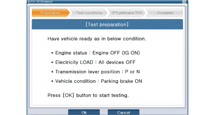
| 2. |
Select "Vehicle S/W management" → "Inspection / Test" → "ETC Performance
Test" on the diagnostic tool menu.
|
| 3. |
Perform "ETC module test" procedure in accordance with the message.
|
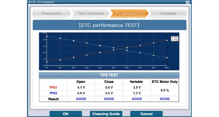
| 4. |
If the test result of the ETC module or TPS signal shows NG, perform
ETC module cleaning.
|
| 1. |
Switch "OFF" the ignition and disconnect the negative (-) battery terminal.
|
| 2. |
Remove the air cleaner assembly.
(Refer to Engine Mechanical System - "Air Cleaner")
|
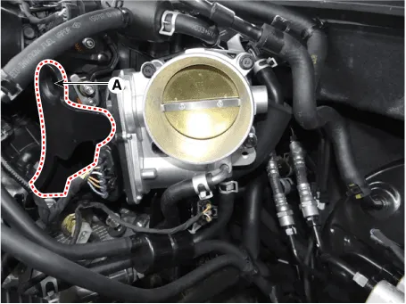
| 3. |
Remove the engine hanger (A) after loosening the mounting bolt.
|
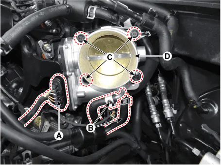
| 4. |
Disconnect the ETC Module connector (A).
|
| 5. |
Disconnect the coolant hoses (B).
|
| 6. |
Remove the ETC module (D) after loosening the mounting bolts (C).
|
Electronic throttle body mounting bolt :
14.7 - 24.5 N.m (1.5 - 2.5 kgf.m, 10.8 - 18.1 lb-ft)
|
|
| 1. |
Remove the ETC Module.
(Refer to Engine Control System - "ETC System")
|
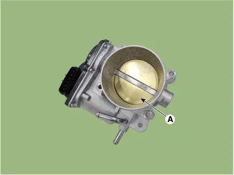
| 2. |
Keep the ETC module plate (A) open.

|
| 3. |
lean the pollutant in the throttle body with a soft cloth moistened
with cleaning fluid.
| •
|
Do not spray cleaning fluid directly onto ETC. Use a
lint free cloth moistened with cleaning fluid.
|
| •
|
Be careful not to clean the coating fluid around the
shaft. If coating fluid is removed, idling control failure
might occur by foreign substance inflow or excessive
air leakage.
|
|
|
| 4. |
After cleaning, re-install the ETC module and then perform the ETC module
learning procedure.
(Refer to Engine Control System - "ETC System" - Adjustment)
|
| • |
Install the component to the specified torque.
|
| • |
Note that internal damage may occur if the component is dropped.
In this case, inspect the component before installation.
|
|
| • |
When cleaning the throttle body, clean the valve and carbon
at the bore with a cloth wet with the cleaner.
|
|
| • |
Do not spray the engine cleaner on the throttle body.
|
|
| • |
Be careful as finger or cloth may get caught in the valve.
|
| • |
When installing the throttle body, keep foreign materials away
from entering the throttle body.
|
|
| 1. |
Install in the reverse order of removal.
|
ETC module learning procedure
Be sure to perform the ETC module learning procedure when replacing or re-installing
the ETC module.
| 1. |
Wait for 1 minute with the ignition switch ON.
|
| 2. |
Start the engine and hold the idle status for 15 minutes.
|
| 3. |
Waif for 1 minute with the ignition switch OFF.
|
| 4. |
Restart the engine, check that the idle speed is stable.
| •
|
Failing to perform the ETC module learning procedure
after replacement or reinstallation may lead to MIL
illumination with DTCs.
|
|
|
Schematic diagrams
ECM Terminal and Input /
Output Signal
ECM Terminal Function
Connector [A]
Pin No
Description
Connected to
1
Ignition Coil (Cylinder #4) control output
Ignition Coil (Cylinder #4)
2
Injector (Cylinder #3) [High] control output
Injector (Cylinder #3)
3
Injector (Cylinder #5) [High] control output
Injector (Cylinder #5)
4
Injector (Cylinder #1) [High] control output
Injector (Cylinder #1)
5
Camshaft Position Sensor (CMPS) [Bank 2 / Exhaust] signal input
Camshaft Position Sensor (CMPS) [Bank 2 / Exhaust]
6
Camshaft Position Sensor (CMPS) [Bank 2 / Intake] signal input
Camshaft Position Sensor (CMPS) [Bank 2 / Intake]
7
Throttle Position Sensor (TPS) 2 signal input
Throttle Position Sensor (TPS) 2
8
-
 
9
Rail Pressure Sensor (RPS) signal input
Rail Pressure Sensor (RPS)
10
CVVT Oil Temperature Sensor (OTS) signal input
CVVT Oil Temperature Sensor (OTS)
11
-
 
12
-
 
13
Sensor power (+5V)
CVVT Oil Temperature Sensor (OTS)
Manifold Absolute Pressure Sensor (MAPS)
14
-
 
15
-
 
16
-
 
17
-
 
18
-
 
19
ETC Motor [-] control output
ETC Motor
20
Heated Oxygen Sensor (HO2S) [Bank 1 / Sensor 1] Heater control output
Heated Oxygen Sensor (HO2S) [Bank 1 / Sensor 1]
21
Heated Oxygen Sensor (HO2S) [Bank 2 / Sensor 1] Heater control output
Heated Oxygen Sensor (HO2S) [Bank 2 / Sensor 1]
22
Ignition Coil (Cylinder #5) control output
Ignition Coil (Cylinder #5
23
Injector (Cylinder #6) [High] control output
Injector (Cylinder #6)
24
Injector (Cylinder #2) [High] control output
Injector (Cylinder #2)
25
Injector (Cylinder #4) [High] control output
Injector (Cylinder #4)
26
Camshaft Position Sensor (CMPS) [Bank 1 / Exhaust] signal input
Camshaft Position Sensor (CMPS) [Bank 1 / Exhaust]
27
Camshaft Position Sensor (CMPS) [Bank 1 / Intake] signal input
Camshaft Position Sensor (CMPS) [Bank 1 / Intake]
28
Intake Air Temperature Sensor (IATS) signal input
Intake Air Temperature Sensor (IATS)
29
Manifold Absolute Pressure Sensor (MAPS) signal input
Manifold Absolute Pressure Sensor (MAPS)
30
-
 
31
-
 
32
-
 
33
-
 
34
Sensor power (+5V)
Camshaft Position Sensor (CMPS) [Bank 1 / Exhaust]
Camshaft Position Sensor (CMPS) [Bank 2 / Intake]
35
-
 
36
Sensor power (+5V)
Camshaft Position Sensor (CMPS) [Bank 1 / Intake]
Camshaft Position Sensor (CMPS) [Bank 2 / Exhaust]
37
-
 
38
Purge Control Solenoid Valve (PCSV) control output
Purge Control Solenoid Valve (PCSV)
39
-
 
40
ETC Motor [+] control output
ETC Motor
41
-
 
42
-
 
43
Ignition Coil (Cylinder #1) control output
Ignition Coil (Cylinder #1)
44
Injector (Cylinder #6) [Low] control output
Injector (Cylinder #6)
45
Injector (Cylinder #3) [Low] control output
Injector (Cylinder #3)
46
Injector (Cylinder #2) [Low] control output
Injector (Cylinder #2)
47
Sensor ground
Camshaft Position Sensor (CMPS) [Bank 1 / Exhaust]
Camshaft Position Sensor (CMPS) [Bank 2 / Intake]
48
Sensor ground
Manifold Absolute Pressure Sensor (MAPS)
Oil Pressure Sensor (OPS)
49
Sensor ground
Camshaft Position Sensor (CMPS) [Bank 1 / Intake]
Camshaft Position Sensor (CMPS) [Bank 2 / Exhaust]
50
-
 
51
-
 
52
-
 
53
-
 
54
Engine Coolant Temperature Sensor (ECTS) signal input
Engine Coolant Temperature Sensor (ECTS)
55
Sensor Shield
Crankshaft Position Sensor (CKPS)
Knock Sensor (KS) #1 [Bank 1]
Knock Sensor (KS) #2 [Bank 2]
56
Sensor power (+5V)
Rail Pressure Sensor (RPS)
57
-
 
58
Sensor ground
Engine Coolant Temperature Sensor (ECTS)
Rail Pressure Sensor (RPS)
59
Sensor ground
Throttle Position Sensor (TPS) 1
Throttle Position Sensor (TPS) 2
60
Variable Intake Solenoid (VIS) Valve 1 control output
Variable Intake Solenoid (VIS) Valve 1
61
Variable Intake Solenoid (VIS) Valve 2 control output
Variable Intake Solenoid (VIS) Valve 2
62
-
 
63
-
 
64
Ignition Coil (Cylinder #2) control output
Ignition Coil (Cylinder #2)
65
Injector (Cylinder #1) [Low] control output
Injector (Cylinder #1)
66
Injector (Cylinder #4) [Low] control output
Injector (Cylinder #4)
67
Injector (Cylinder #5) [Low] control output
Injector (Cylinder #5)
68
Crankshaft Position Sensor (CKPS) [High] signal input
Crankshaft Position Sensor (CKPS)
69
Crankshaft Position Sensor (CKPS) [Low] signal input
Crankshaft Position Sensor (CKPS)
70
-
 
71
-
 
72
Oil pressure switch signal input
Oil Pressure Sensor (OPS)
73
-
 
74
-
 
75
Throttle Position Sensor (TPS) 1 signal input
Throttle Position Sensor (TPS) 1
76
Knock Sensor (KS) [Bank 1] [Low] signal input
Knock Sensor (KS) [Bank 1]
77
Knock Sensor (KS) [Bank 2] [Low] signal input
Knock Sensor (KS) [Bank 2]
78
Sensor ground
Heated Oxygen Sensor (HO2S) [Bank 2 / Sensor 2]
79
Rc/Rp (Pump Cell Voltage)
Heated Oxygen Sensor (HO2S) [Bank 2 / Sensor 1]
80
VS+ (NERNST Cell Voltage)
Heated Oxygen Sensor (HO2S) [Bank 2 / Sensor 1]
81
Heated Oxygen Sensor (HO2S) [Bank 2 / Sensor 2] signal input
Heated Oxygen Sensor (HO2S) [Bank 2 / Sensor 2]
82
VS+ (NERNST Cell Voltage)
Heated Oxygen Sensor (HO2S) [Bank 1 / Sensor 1]
83
Rc (Compensative Resistance)
Heated Oxygen Sensor (HO2S) [Bank 1 / Sensor 1]
84
Oil Pressure Solenoid Valve control output
Oil Pressure Solenoid Valve
85
Ignition Coil (Cylinder #6) control output
Ignition Coil (Cylinder #6)
86
Ignition Coil (Cylinder #3) control output
Ignition Coil (Cylinder #3)
87
Fuel Pressure Control Valve (FPCV) [High] control output
Fuel Pressure Control Valve (FPCV)
88
Fuel Pressure Control Valve (FPCV) [Low] control output
Fuel Pressure Control Valve (FPCV)
89
Heated Oxygen Sensor (HO2S) [Bank 2 / Sensor 2] Heater control output
Heated Oxygen Sensor (HO2S) [Bank 2 / Sensor 2]
90
Heated Oxygen Sensor (HO2S) [Bank 1 / Sensor 2] Heater control output
Heated Oxygen Sensor (HO2S) [Bank 1 / Sensor 2]
91
CVVT Oil Control Valve (OCV) [Bank 2 / Exhaust] control output
CVVT Oil Control Valve (OCV) [Bank 2 / Exhaust]
92
CVVT Oil Control Valve (OCV) [Bank 1 / Exhaust] control output
CVVT Oil Control Valve (OCV) [Bank 1 / Exhaust]
93
Variable Force Solenoid (VFS) [Bank 2 / Intake] control output
Variable Force Solenoid (VFS) [Bank 2 / Intake]
94
Variable Force Solenoid (VFS) [Bank 1 / Intake] control output
Variable Force Solenoid (VFS) [Bank 1 / Intake]
95
-
 
96
Sensor power (+5V)
Throttle Position Sensor (TPS) 1
Throttle Position Sensor (TPS) 2
97
Knock Sensor (KS) [Bank 1] [High] signal input
Knock Sensor (KS) [Bank 1]
98
Knock Sensor (KS) [Bank 2] [High] signal input
Knock Sensor (KS) [Bank 2]
99
Sensor ground
Heated Oxygen Sensor (HO2S) [Bank 1 / Sensor 2]
100
-
 
101
Rc (Compensative Resistance)
Heated Oxygen Sensor (HO2S) [Bank 2 / Sensor 1]
102
VS-/IP- (Common ground)
Heated Oxygen Sensor (HO2S) [Bank 2 / Sensor 1]
103
Heated Oxygen Sensor (HO2S) [Bank 1 / Sensor 2] signal input
Heated Oxygen Sensor (HO2S) [Bank 1 / Sensor 2]
104
VS-/IP- (Common ground)
Heated Oxygen Sensor (HO2S) [Bank 1 / Sensor 1]
105
Rc/Rp (Pump Cell Voltage)
Heated Oxygen Sensor (HO2S) [Bank 1 / Sensor 1]
Connector [K]
Pin No
Description
Connected to
1
ECM ground
Chassis ground
2
ECM ground
Chassis ground
3
Battery power (B+)
Main Relay
4
ECM ground
Chassis ground
5
Battery power (B+)
Main Relay
6
Battery power (B+)
Main Relay
7
-
 
8
-
 
9
-
 
10
-
 
11
-
 
12
-
 
13
Sensor ground
A/C Pressure Transducer (APT)
14
Immobilizer communication line
Immobilizer Control Module
15
Fuel Level Sender (FLS) signal input [Fuel pump]
Fuel Level Sender (FLS)
16
-
 
17
-
 
18
-
 
19
-
 
20
Sensor power (+5V)
Accelerator Position Sensor (APS) 1
21
Main Relay control output
Main Relay
22
-
 
23
-
 
24
-
 
25
-
 
26
-
 
27
-
 
28
Accelerator Position Sensor (APS) 2 signal input
Accelerator Position Sensor (APS) 2
29
-
 
30
-
 
31
-
 
32
Fuel Level Sender (FLS) signal input [Sub Fuel Sender]
Sub Fuel Level Sender
33
Fuel Pump Relay control output
Fuel Pump Relay
34
-
 
35
Sensor power (+5V)
A/C Pressure Transducer (APT)
36
Sensor power (+5V)
Accelerator Position Sensor (APS) 2
37
-
 
38
Vehicle speed signal input
VDC control module
39
-
 
40
-
 
41
Start signal input
Start Relay
42
-
 
43
-
 
44
-
 
45
-
 
46
-
 
47
Sensor ground
Accelerator Position Sensor (APS) 2
48
-
 
49
Brake Switch [Test] signal input
Brake Switch
50
-
 
51
-
 
52
Sensor ground
Accelerator Position Sensor (APS) 1
53
-
 
54
-
 
55
-
 
56
-
 
57
-
 
58
-
 
59
-
 
60
P-CAN [Low]
Other control module, Data Link Connector (DLC), Multi-Purpose Check Connector
61
-
 
62
-
 
63
-
 
64
A/C Pressure Transducer (APT) signal input
A/C Pressure Transducer (APT)
65
-
 
66
-
 
67
-
 
68
-
 
69
LIN (Local Interconnect Network) Serial Bus Line
Battery Sensor
70
-
 
71
Cooling Fan Relay control output
Cooling Fan Relay
72
Engine speed signal output
Integrated Body Control Unit (IBU)
73
-
 
74
-
 
75
-
 
76
-
 
77
P-CAN [High]
Other control module, Data Link Connector (DLC), Multi-Purpose Check Connector
78
-
 
79
Start Relay control output
Start Relay
80
-
 
81
-
 
82
Accelerator Position Sensor (APS) 1 signal input
Accelerator Position Sensor (APS) 1
83
Brake Switch [Light] signal input
Brake Switch
84
-
 
85
-
 
86
-
 
87
-
 
88
-
 
89
-
 
90
-
 
91
-
 
ECM Terminal Input/ Output signal
Connector [A]
Pin No
Description
Condition
Type
Level
1
Ignition Coil (Cylinder #4) control output
Idle
Pulse
Vpeak = 400V
Frequency : 0 - 58.
Description and operation
Description
Mounted inside the Manifold Absolute Pressure Sensor, Intake Air Temperature
Sensor (IATS) detects the intake air temperature.
Other information:
Components and components location
Component Location
1. Heater unit assembly
Components
1. Heater core assembly
2. Heater unit pad
3. Heater lower cover
4. Drain hose
5.


