Hyundai Palisade (LX2): Air conditioning System / Refrigerant Line
Components and components location
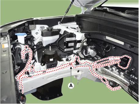
[Isometric view]

1. Front suction & Liquid pipe
assembly
|
|
[Top view]
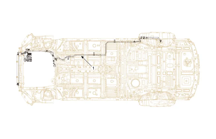
1. Front suction & Liquid pipe
assembly
|
|
Repair procedures
[Front suction & Liquid pipe assembly]
| 1. |
If a compressor is available, the air conditioner is operated for a
few minutes in the engine idle state and then the engine is stopped.
|
| 2. |
Disconnect the negative (-) battery terminal.
|
| 3. |
Recover the refrigerant with a recovery/charging station.
|
| 4. |
Remove the engine cover.
(Refer to Engine Mechanical System - "Engine Cover")
|
| 5. |
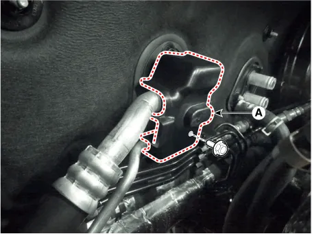
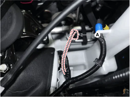
Loosen the mounting nut and remove the expansion valve cover (A).
|
Tightening torque :
8.8 - 13.7 N.m (0.9 - 1.4 kgf.m, 6.5 - 10.1 lb-ft)
|
|
| 6. |
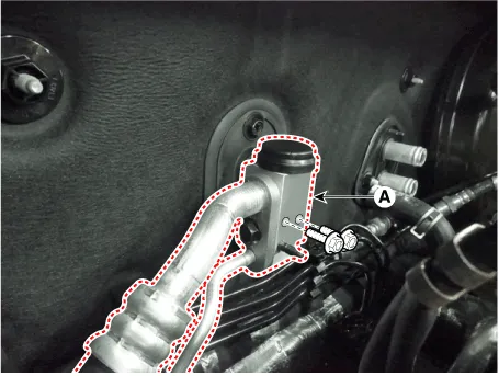
Loosen the mounting bolts and separate the expansion valve (A) fron
evaporator core.
|
Tightening torque :
8.8 - 13.7 N.m (0.9 - 1.4 kgf.m, 6.5 - 10.1 lb-ft)
|
|
| 7. |
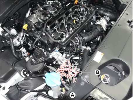
Loosen the mounting nuts and separate the suction line (A), discharge
line (B).
|
Tightening torque :
19.6 - 23.5 N.m (2.0 - 2.4 kgf.m, 14.5 - 17.4 lb-ft)
|
|
| 8. |
Press the lock pin and separate the APT (Air conditioning Pressure Transducer)
sensor connector (A).
|
| 9. |
Remove the engine room under cover.
(Refer to Engine Mechanical System - "Engine Room Under Cover")
|
| 10. |
Remove the engine mounting braket.
(Refer to Engine Mechanical System - "Engine Mounting")
|
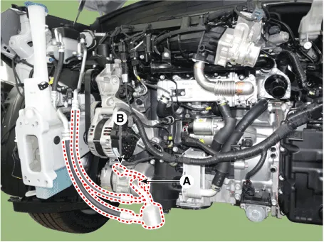
| 11. |
Separate the compressor suction line (A) and discharge line (B) connection
nuts and disconnect the line.
|
Tightening torque :
20.9 - 31.2 N.m (2.1 - 3.2 kgf.m, 15.4 - 23.0 lb-ft)
|
| •
|
Be careful not to damage the parts located under the
vehicle (floor under cover, fuel filter, fuel tank and
canister) when raising the vehicle using the lift.
(Refer to General Information - "Lift and Support Points")
|
|
|
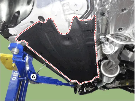
| 12. |
Loosen the mounting bolts, nuts and remove the engine room under cover
[RH] (A).
|
Tightening torque
8.8 - 13.7 N.m (0.9 - 1.4 kgf.m, 6.5 - 10.1 lb-ft)
|
|
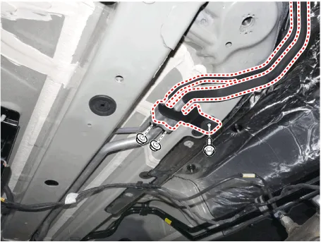
| 13. |
Remove the refrigerant pipe line mounting nuts and braket bolt.
|
Tightening torque :
Nut : 8.8 - 13.7 N.m (0.9 - 1.4 kgf.m, 6.5 - 10.1 lb-ft)
Bolt : 7.8 - 11.8 N.m (0.8 - 1.2 kgf.m, 5.8 - 8.7 lb-ft)
|
|
| 14. |
Loosen the mounting bolt and remove the Front suction & Liquid pipe
assembly (A).
|
Tightening torque :
7.8 - 11.8 N.m (0.8 - 1.2 kgf.m, 5.8 - 8.7 lb-ft)
|
|
| 15. |
To install, reverse removal procedure.
|
| • |
Plug or cap the lines immediately after disconnecting them to
avoid moisture and dust contamination.
|
| • |
Tighten the bolt or nut joint to the specified torque.
|
| • |
Using a gas leak detector, check for refrigerant leakage.
|
| • |
Evacuate air in the refrigeration system and charge system with
refrigerant.
|
|
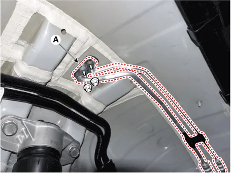
[Rear Suction & Liquid Pipe Assembly]
| 1. |
If a compressor is available, the air conditioner is operated for a
few minutes in the engine idle state and then the engine is stopped.
|
| 2. |
Disconnect the negative (-) battery terminal.
|
| 3. |
Recover the refrigerant with a recovery/charging station.
|
| 4. |
Remove the rear wheel guard [RH].
(Refer to Body - "Rear Wheel Guard")
|
| 5. |
Loosen the mounting nuts and separate the suction line, discharge line
(A).
|
Tightening torque :
19.6 - 23.5 N.m (2.0 - 2.4 kgf.m, 14.5 - 17.4 lb-ft)
|
|
| 6. |
Loosen the mounting bolts, nuts and remove the engine room under cover
[RH] (A).
|
Tightening torque :
8.8 - 13.7 N.m (0.9 - 1.4 kgf.m, 6.5 - 10.1 lb-ft)
|

|
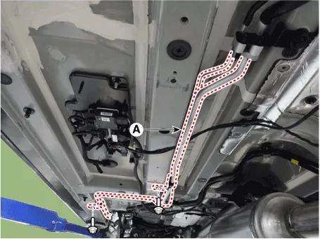
| 7. |
Remove the refrigerant pipe line mounting nuts.
|
Tightening torque :
8.8 - 13.7 N.m (0.9 - 1.4 kgf.m, 6.5 - 10.1 lb-ft)
|

|
| 8. |
Loosen the mounting bolt and remove the Rear suction & Liquid pipe assembly
(A).
|
Tightening torque :
7.8 - 11.8 N.m (0.8 - 1.2 kgf.m, 5.8 - 8.7 lb-ft)
|
|
| 9. |
To install, reverse removal procedure.
|
| • |
Plug or cap the lines immediately after disconnecting them to
avoid moisture and dust contamination.
|
| • |
Tighten the bolt or nut joint to the specified torque.
|
| • |
Using a gas leak detector, check for refrigerant leakage.
|
| • |
Evacuate air in the refrigeration system and charge system with
refrigerant.
|
|
Repair procedures
Oil Specification
1.
The R-134a or R-1234yf system requires synthetic (PAG) compressor oil
whereas the R-12 system requires mineral compressor oil.
Description and operation
Description
The compressor is the power unit of the A/C system.
It is located on the side of engine block and driven by a V-belt of the engine.
Other information:
Description and operation
Description
The mode control actuator is located at the heater unit.
It adjusts the position of the mode door by operating the mode control actuator
based on the signal of the A/C control unit. Pressing the mode select switch
makes the mode control actuator shift in order of Vent → Bi-Level →


