Hyundai Palisade (LX2): Motor Driven Power Steering / Steering Gear Box
Components and components location
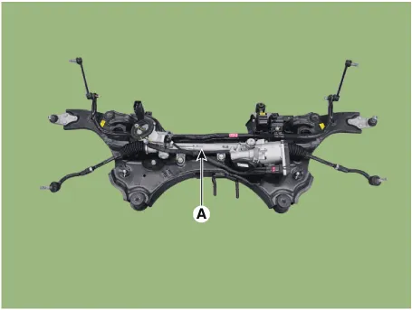
| Components |
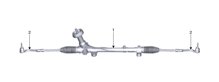
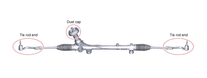
| 1. Steering gera box |
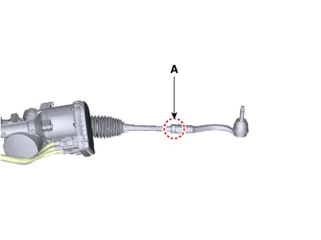
2 Tie rod end |
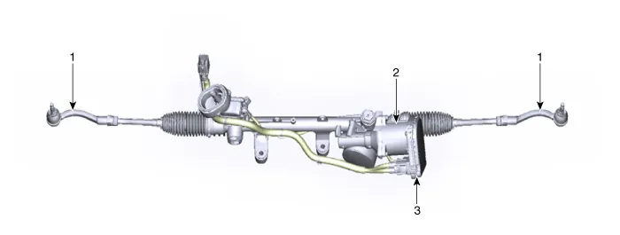
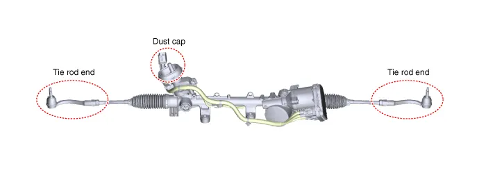
| 1. Tie rod end 2. R-MDPS Motor |
3. R-MDPS ECU |
Repair procedures
| Removal and Installation |
|

| 1. |
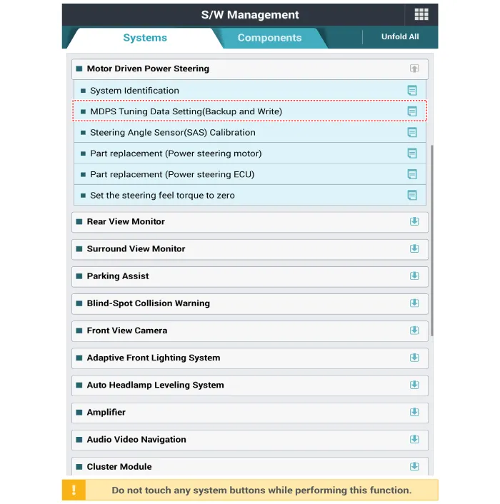
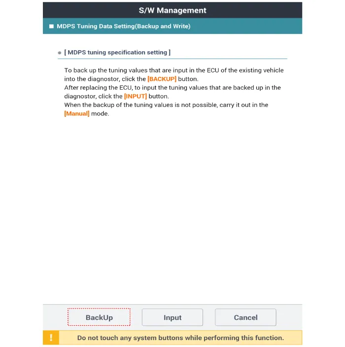
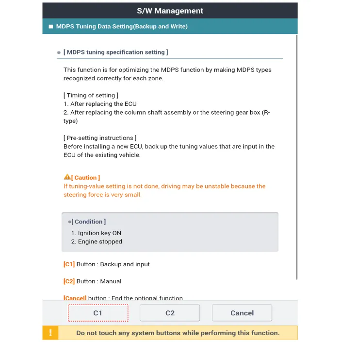
Perform the "ECU data backup" by diagnostic tool following in the order
below.
|


| 1. |
Turn the ignition switch OFF and disconnect the battery negative (-)
cable.
|
| 2. |
Turn the steering wheel so that the front wheels are placed in the straight
ahead position.
|
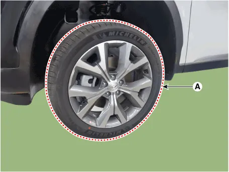
| 3. |
Remove the front wheel and tire (A) from front hub.
|

| 4. |
Disconnect the stabilizer link with the front strut assembly after loosening
the nut (A).
|

| 5. |
Remove the tie rod end ball joint.
|
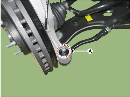
| 6. |
Rmove the split pin and nut (A).
|
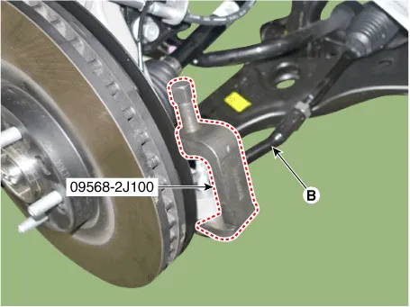
| 7. |
Remove the lower arm from the knuckle by using the SST (09568-4R100).
|
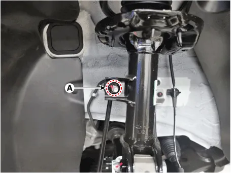
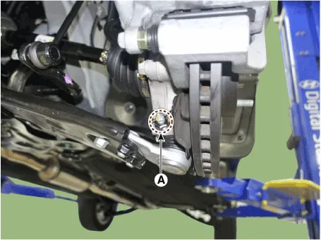
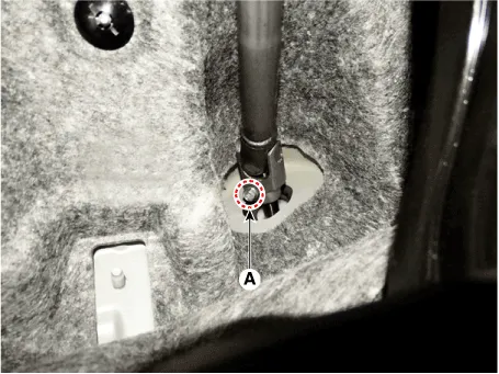
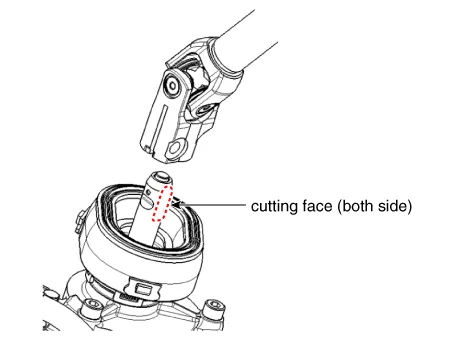
| 8. |
Loosen the bolt (A) and then disconnect the universal joint assembly
from the pinion of the steering gear box.
|

| 9. |
Remove the under cover.
(Refer to Engine Mechanical System - "Engine Room Under Cover")
|
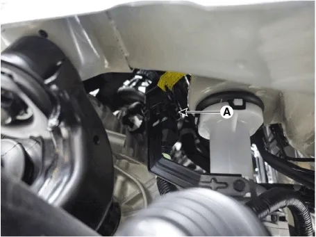
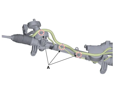
| 10. |
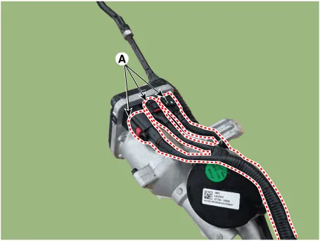
Disconnect the R-MDPS main connector (A). [R-MDPS Type only]
|
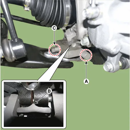
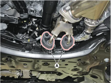
| 11. |
Remove the muffler rubber hanger (A).
|
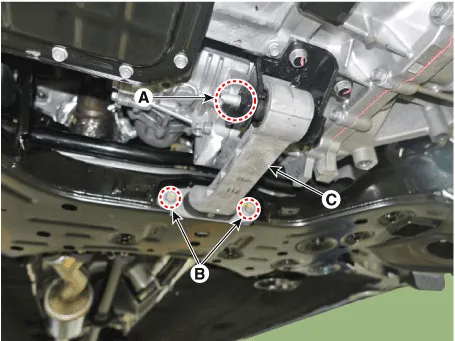
| 12. |
Remove the roll rod bracket (C) by loosening the bolt (A), (B).
|
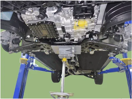
| 13. |
Remove the subframe by loosening the mounting bolts and nuts.
|

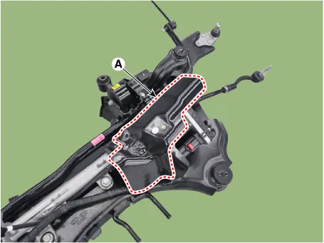
| 14. |
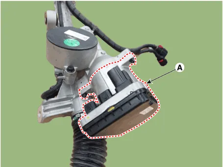
Remove the heated protector (A).
[C-MDPS]
[R-MDPS]
|
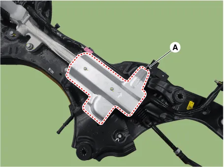
| 15. |
Remove the steering gearbox (A) from the front sub frame by loosening
the mounting bolts.
[C-MDPS]
[R-MDPS]
|

| 16. |
Install in the reverse order of removal.
|
| 17. |
Check the alignment.
(Refer to Tires / Wheels - "Alignment")
|
| 18. |
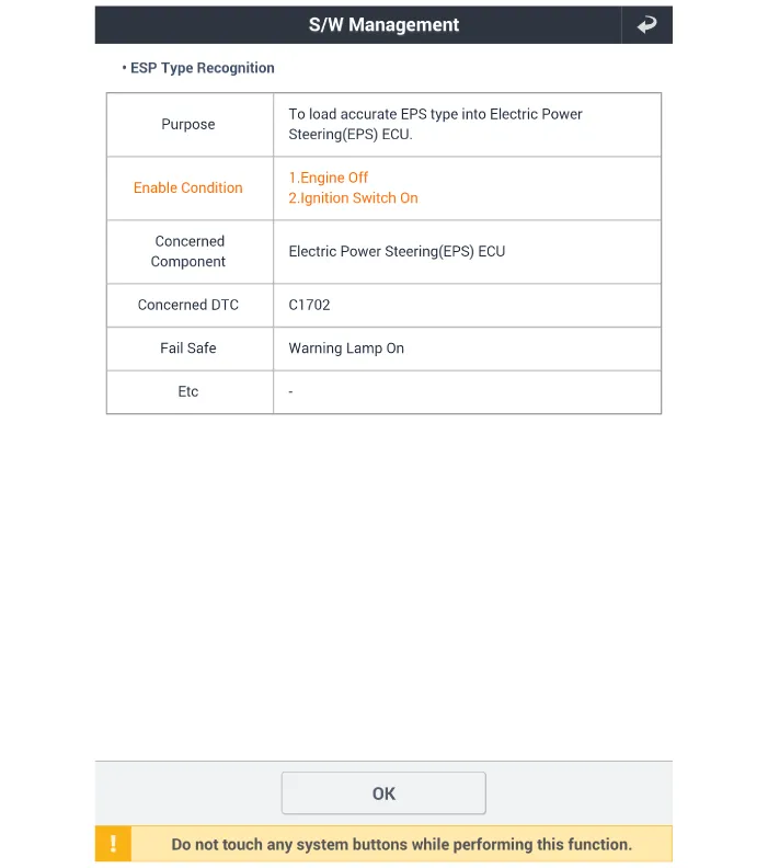
Conduct the "EPS Type Recognition" by diagnostic tool.
(Refer to MDPS motor - "Diagnosis with GDS")
|
| 19. |
Perform the "ECU data restore" by diagnostic tool following in the order
below. [R-MDPS Only]
|


| Replacement |
|

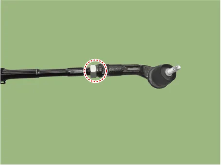
| 1. |
Remove the tie rod end after loosening the nut.
|

| 2. |
Replace with new parts.
|
| 3. |
Check the alignment.
(Refer to Tires / Wheels - "Alignment")
|
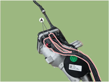
| 1. |
Disconnect the power pack connector (A).
|
| 2. |
Replace the power pack (A) after loosening the mounting bolts.
|
| 3. |
In case of the power pack replacement, replace the power pack only and
reuse the existing short gear.
In case of the short gear replacement, replace the short gear only and
reuse the existing power pack.
|
| 4. |
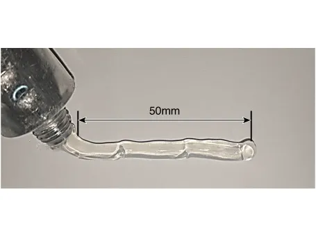
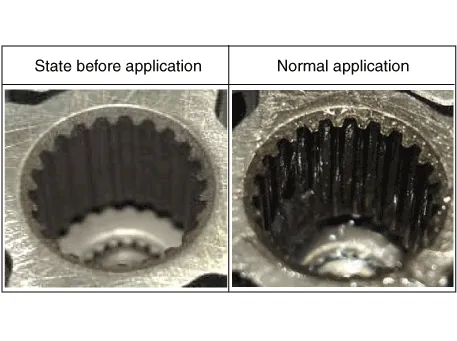
Apply grease to the serration area of the new power pack.
|

| 5. |
After replacing the power pack motor, "EPS type recognition" and "Steering
Angle Sensor (SAS) Calibration" must be done.
|
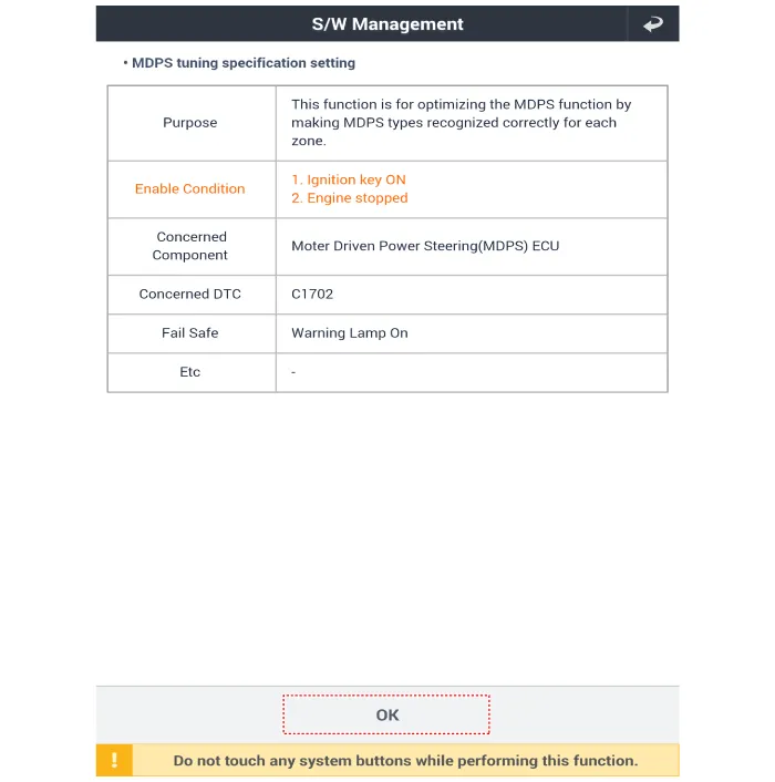
| 1. |
Disconnect the power pack connector (A).
|
| 2. |
Replace the lead wire after disconnecting the fixed clip (A).
Precautions the MDPS specification recognition or steering angle initialization.
- Use the scan tool to check whether the battery voltage is normal before
recognizing the MDPS specification or initializing the steering angle.
- Be careful not to disconnect any connectors connected to the vehicle
or scan tool during the MDPS specification recognition or steering angle
initialization.
- When the MDPS specification recognition or steering angle initializing
is completed, turn off the IG switch and wait for more than 10 seconds,
and then turn on the engine to check the normal operation.
|
| 1. |
Connect the GDS diagnostic tool to the vehicle's self-diagnostic connector.
|
| 2. |
Key on the Ignition switch.
|
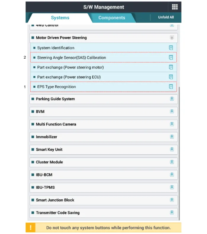
| 3. |
After Selecting the "vehicle model" and "system", select the "EPS Type
Recognition" on GDS vehicle selection screen.
[MDPS Type Recognition]
[MDPS Type Recognition 1]
|

Repair procedures Replacement [C-MDPS] 1. Turn the ignition switch OFF and disconnect the battery negative (-) cable.
Other information:
Hyundai Palisade (LX2) 2020-2026 Service Manual: Heater Unit
Components and components location Component Location 1. Heater unit assembly Components 1. Heater core assembly 2. Heater unit pad 3. Heater lower cover 4. Drain hose 5.
Hyundai Palisade (LX2) 2020-2026 Service Manual: Special service tools
Special Service Tools Tool Name / Number Illustration Description LKA Compensator (09890-3V100) Used for compensating front view camera unit Tolerance Compensation Plate for Surround View Monitoring (09957-CM100)
Categories
- Manuals Home
- Hyundai Palisade Owners Manual
- Hyundai Palisade Service Manual
- Automatic Transaxle System (A8LF1)
- Engine Mechanical System
- Removing and Storing the Spare Tire
- New on site
- Most important about car
