Hyundai Palisade (LX2): Steering wheel / Heated Steering wheel
Description and operation
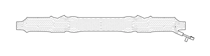
Heated pads to grip the steering grip makes the fever.
Heated pad
Specifications
Item
|
Specification
|
Voltage
|
13.5 V
|
Heated pad resistance
|
1.68 Ω ± 10 %
|
NTC resistance
|
10.0 kΩ ± 5 % (25 °C)
|
Schematic diagrams


Terminal Function
Item
|
Pin
|
Function
|
Wire color
|
Pad
|
A
|
HEATER
|
Red / Black
|
B
|
GND
|
Brown / Black
|
C
|
NTC-
|
Black
|
D
|
NTC+
|
Black
|
Remote control
|
A
|
GND
|
Black
|
B
|
BAT
|
Red
|
C
|
LED
|
Green
|
D
|
SWITCH
|
White
|
Repair procedures
| 1. |
Measure a resistance of NTC and Heated pad.
| – |
NTC resistance - 10.0 kΩ ± 5 % (25 ° C)
|
| – |
Heated pad resistance - 1.68 Ω ± 10%
|
|
| 2. |
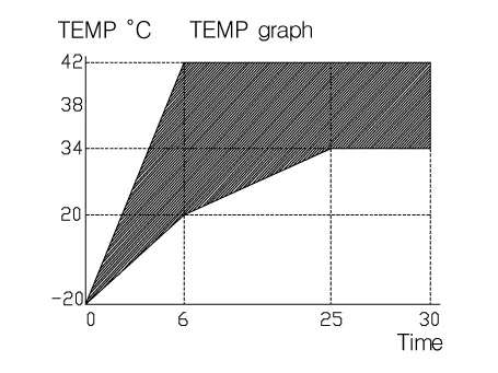
Measure a temperature.
| – |
The temperature of wheel surface grip must rise from -20 °C
to 20 °C within 6 minute
|
| – |
The temperature of wheel surface grip must keep 38 °C ± 4 °C
after 25 minute
|
| – |
At that time switch on, all measure point (1 - 8)
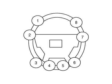
|
|
Removal
1.
Turn the ignition switch OFF and disconnect the battery negative (-)
cable.
2.
Turn the steering wheel so that the front wheels can face straight ahead.
Other information:
Schematic diagrams
Circuit Diagram
Repair procedures
Removal
1.
Disconnect the negative (-) battery terminal.
2.
Remove the inside rear view mirror cover (A) and rain sensor cover (B).
Trouble Symptom Charts
Component Parts and Function Outline
Component part
Function
Cruise Control Switch
Input the set speed and distance to the SCC ECU.
Instrument Cluster
Display various information inputted from SCC.
