Hyundai Palisade (LX2): Fuel Delivery System / Fuel Pressure Sensor (FPS)
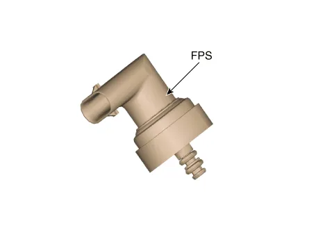
Description and operation
| Description |

Specifications
| Specification |
|
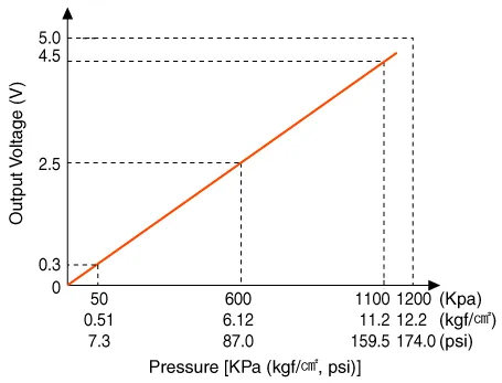
Pressure [kPa (kgf/cm², psi)] |
Output Voltage (V) |
|
50 (0.51, 7.3) |
0.3 |
|
600 (6.12, 87.0) |
2.5 |
|
1100 (11.2, 159.5) |
4.5 |
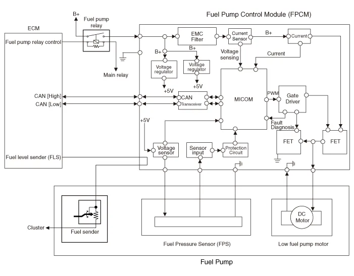
Schematic diagrams
| Circuit Diagram |
| Terminal Illustration |

| Terminal Function |
|
No |
Function |
Connected to |
|
1 |
Fuel Pressure sensor (FPS) power supply |
Fuel Pump Control Module (FPCM) |
|
2 |
Fuel Pressure sensor (FPS) signal input |
Fuel Pump Control Module (FPCM) |
|
3 |
Fuel Pressure sensor (FPS) groun |
Fuel Pump Control Module (FPCM) |
Repair procedures
| Inspection |
| 1. |
Connect the diagnostic tool on the Data Link Connector (DLC).
|
| 2. |
Check the output voltage of fuel pressure sensor (FPS).
|
|
Pressure [kPa (kgf/cm², psi)] |
Output Voltage (V) |
|
50 (0.51, 7.3) |
0.3 |
|
600 (6.12, 87.0) |
2.5 |
|
1100 (11.2, 159.5) |
4.5 |
| Removal |
| 1. |
Release the residual pressure in fuel line.
(Refer to Fuel Delivery System - "Release Residual Pressure in Fuel
Line")
|
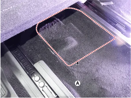
| 2. |
Remove the floor carpet service cover (A).
|
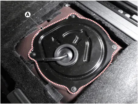
| 3. |
Remove the fuel pump service cover (A) after loosening the mounting
screws.
|
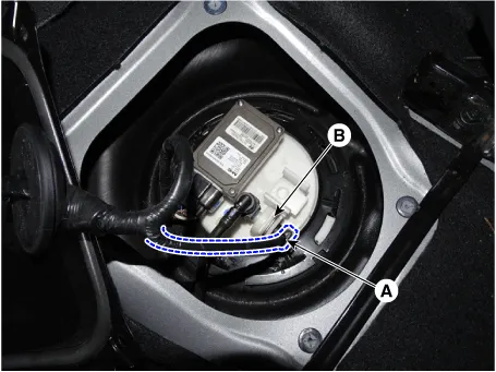
| 4. |
Disconnect the fuel pressure sensor connector (A).
|
| 5. |
Remove the fuel pressure sensor fixing pin (B).
|
| 6. |
Remove the fuel pressure sensor from the fuel pump.
|
| Installation |
| 1. |
Install in the reverse order of removal.
|
Description and operation Description The fuel pump control module (FPCM) is installed on the right side of the fuel tank and controls the DC motor mounted inside the low pressure fuel pump.
Repair procedures Removal 1. Remove the fuel pump. (Refer to Fuel Delivery System - "Fuel Pump") 2.
Other information:
Hyundai Palisade (LX2) 2020-2026 Service Manual: General safety information and caution
Instructions (R-134a) When Handling Refrigerant 1. R-134a liquid refrigerant is highly volatile. A drop on the skin of your hand could result in localized frostbite. When handling the refrigerant, be sure to wear gloves.
Hyundai Palisade (LX2) 2020-2026 Service Manual: Rear Heater Unit
Components and components location Component Location 1. Rear Heater & A/C Unit Repair procedures Replacement • Be careful not to damage the parts located under the vehicle
Categories
- Manuals Home
- Hyundai Palisade Owners Manual
- Hyundai Palisade Service Manual
- Automatic Transaxle System (A8LF1)
- Power Outlet
- Repair procedures
- New on site
- Most important about car
