Hyundai Palisade (LX2): Cruise Control System / Cruise Control Switch
Components and components location
| Components |
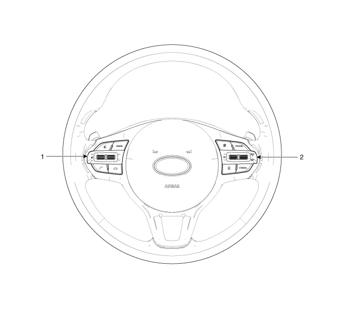
| 1. Left Remote Control Switch (Audio + Hands free + Voice) |
2. Right Remote Control Switch (Cruise + Trip Computer) |
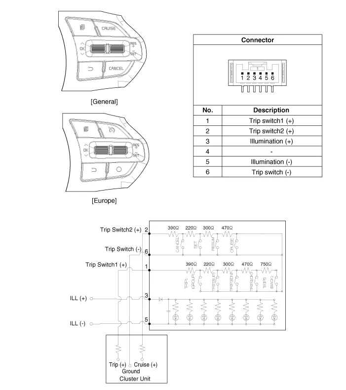
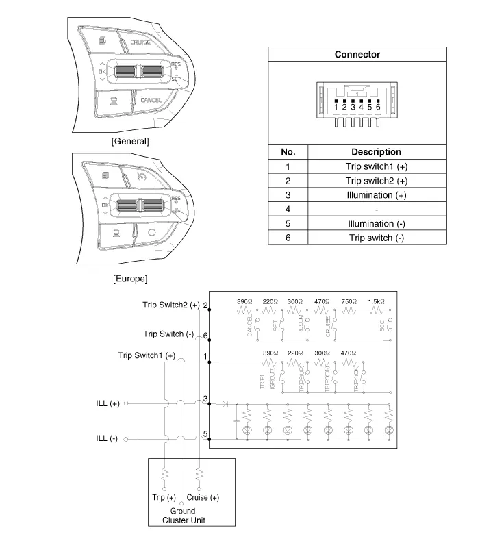
Schematic diagrams
| Circuit Diagram |

| [Trip + ACC] |
| [Trip + ASCC] |
Repair procedures
| Inspection |
| 1. |
Check for resistance between terminals in each switch position (RH).
[RH : Cruise + Trip]
|
| Removal |
| 1. |
Disconnect the negative (-) battery terminal.
|
| 2. |
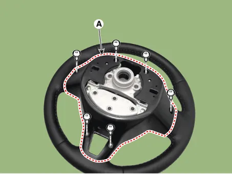
Remove the steering wheel assembly.
(Refer to Steering System - "Steering Wheel")
|
| 3. |
Remove the steering back cover (A) after loosening the mounting screws.
|
| 4. |
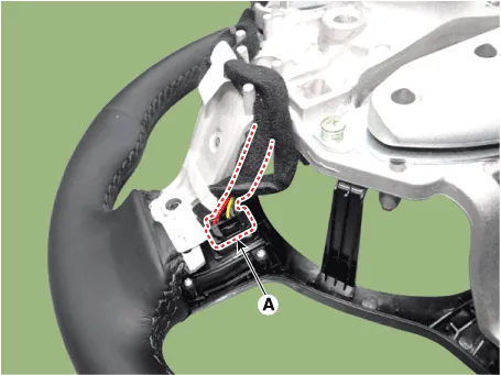
Disconnect the steering wheel remote control connector (A).
[LH]
[RH]
|

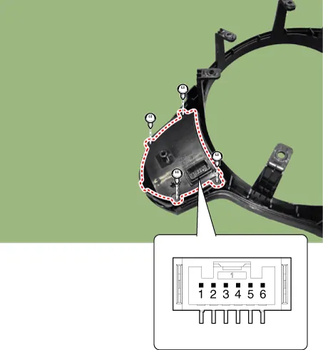
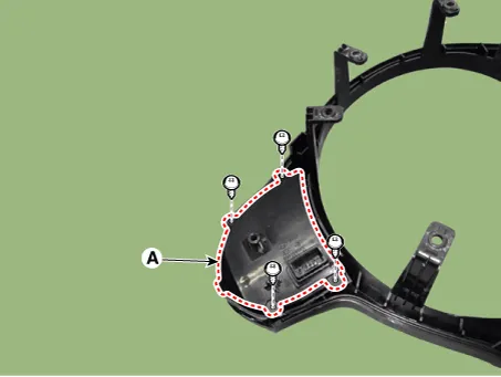
| 5. |
Remove the steering wheel remote control assembly (A) after loosening
the mounting screws.
|

| 6. |
Remove the steering wheel remote control (A) after loosening the mounting
screws.
|
| Installation |
| 1. |
Install the steering wheel remote control.
|
| 2. |
Install the steering wheel remote control assembly.
|
| 3. |
Connect the steering wheel remote control connector.
|
| 4. |
Install the steering back cover.
|
| 5. |
Install the steering wheel and driver airbag module.
|
| 6. |
Connect the negative (-) battery terminal.
|
Trouble Symptom Charts Trouble Symptom 1 Trouble Symptom 2 Trouble symptom Probable cause Remedy The set vehicle speed varies greatly upward or downward "Surging" (repeated alternating acceleration and deceleration) occurs after setting Malfunction of the vehicle speed sensor circuit Repair the vehicle speed sensor system, or replace the part Malfunction of ECM Check input and output signals at ECM Trouble Symptom 3 Trouble symptom Probable cause Remedy The CC system is not canceled when the brake pedal is depressed Damaged or disconnected wiring of the brake pedal switch Repair the harness or replace the brake pedal switch Malfunction of the ECM signals Check input and output signals at ECM Trouble Symptom 4 Trouble symptom Probable cause Remedy The CC system is not canceled when the shift lever is moved to the "N" position (It is canceled, however, when the brake pedal is depressed) Damaged or disconnected wiring of inhibitor switch input circuit Repair the harness or repair or replace the inhibitor switch Improper adjustment of inhibitor switch Malfunction of the ECM signals Check input and output signals at ECM Trouble Symptom 5 Trouble symptom Probable cause Remedy Cannot decelerate (coast) by using the "SET/–" switch Temporary damaged or disconnected wiring of "SET/–" switch input circuit Repair the harness or replace the "SET/–" switch Malfunction of the ECM signals Check input and output signals at ECM Trouble Symptom 6 Trouble symptom Probable cause Remedy Cannot accelerate or resume speed by using the "RES/+" switch Damaged or disconnected wiring, or short circuit, or "RES/+" switch input circuit Repair the harness or replace the "RES/+" switch Malfunction of the ECM signals Check input and output signals at ECM Trouble Symptom 7 Trouble symptom Probable cause Remedy CC system can be set while driving at a vehicle speed of less than 40km/h (25mph), or there is no automatic cancellation at that speed Malfunction of the vehicle-speed sensor circuit Repair the vehicle speed sensor system, or replace the part Malfunction of the ECM signals Check input and output signals at ECM Trouble Symptom 8 Trouble symptom Probable cause Remedy The cruise main switch indicator lamp does not illuminate (although CC system is normal) Damaged or disconnected bulb of cruise main switch indicator lamp Repair the harness or replace the part.
Other information:
Hyundai Palisade (LX2) 2020-2026 Service Manual: General safety information and caution
Instructions (R-134a) When Handling Refrigerant 1. R-134a liquid refrigerant is highly volatile. A drop on the skin of your hand could result in localized frostbite. When handling the refrigerant, be sure to wear gloves.
Hyundai Palisade (LX2) 2020-2026 Service Manual: Heater & A/C Control Unit (DATC)
Components and components location Component Connector Pin Function Connector PIN No Pin Function Connector PIN No Pin Function A 1 Battery A 21 IGN2 2
Categories
- Manuals Home
- Hyundai Palisade Owners Manual
- Hyundai Palisade Service Manual
- Electrochromatic Mirror (ECM) with homelink system
- General Tightening Torque Table
- Electronic Child Safety Lock System
- New on site
- Most important about car
