Hyundai Palisade (LX2): Downhill Brake Control (DBC) / DBC operation
Downhill Brake Control disabled. Control vehicle speed
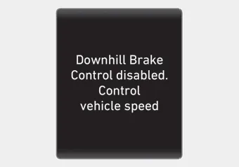
When the DBC system is not working properly this warning message will appear on the LCD display and you will hear a warning sound. If this occurs, control the vehicle speed by depressing the brake pedal.
WARNING
Always turn off the DBC on normal roads. The DBC might activate inadvertently from the standby mode when driving through speed bumps or making sharp curves.
Information
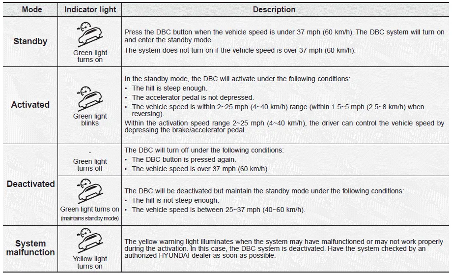
- Noise or vibration may occur from the brakes when the DBC is activated.
- The rear stop light comes on when DBC is activated.
NOTICE
- The DBC may not deactivate on steep inclines even though the brake or accelerator pedal is depressed.
- The DBC system may not always maintain the vehicle speed at a certain speed.
- The DBC does not operate when:
- The gear is in P (Park).
- The ESC is activated.
The Downhill Brake Control (DBC) feature assists the driver to descend down a steep hill without having to depress the brake pedal. The system automatically applies the brakes to maintain the vehicle speed below a certain speed and allows the driver to concentrate on steering the vehicle down hill.
Trailer Stability Assist system helps stabilize the vehicle and trailer when the trailer sways or oscillates. There are various reasons making the vehicle sway and oscillate.
Other information:
Hyundai Palisade (LX2) 2020-2026 Service Manual: Compressor oil
Repair procedures Oil Specification 1. The R-134a or R-1234yf system requires synthetic (PAG) compressor oil whereas the R-12 system requires mineral compressor oil. The two oils must never be mixed. 2.
Hyundai Palisade (LX2) 2020-2026 Service Manual: Troubleshooting
Troubleshooting 1) After replacing H/UNIT, always check that the system operates properly. 2) If the failure persists after replacing the H/UNIT, do not replace the unit.
Categories
- Manuals Home
- Hyundai Palisade Owners Manual
- Hyundai Palisade Service Manual
- Power Outlet
- Lift and Support Points
- Rear Heater Unit
- New on site
- Most important about car
