Hyundai Palisade: Heater / Heater Unit
Components and components location


1. Heater core assembly
2. Heater unit pad
3. Heater lower cover
4. Drain hose
5. Heater blind case
6. Heater case [RH]
7. Temperature actuator [RH]
|
8. Heater case [LH]
9. FOOT Door assembly
10. Temperature door assembly
11. Mode actuator
12. PTC Heater
13. Vent door assembly [LH]
14. Vent door assembly [RH]
|
15. DEF Door assembly
16. Heater unit pad
17. Heater pipe cover
18. Temperature actuator [LH]
19. Duct seal assembly
21. Evaporator assembly
|
Repair procedures
1. |
Disconnect the negative (-) battery terminal.
|
2. |
Recover the refrigerant with a recovery/recycling/charging station.
|
3. |
When the engine is cool, drain the engine coolant from the radiator.
(Refer to Engine Mechanical System - "Coolant")
|
4. |
Remove the cowl top cover.
(Refer to Body - "Cowl Top Cover")
|
5. |
Loosen the mounting nut and remove the expension valve cover (A).
Tightening torque :
8.8 - 13.7 N.m (0.9 - 1.4 kgf.m , 6.5 - 10.1 lb-ft)
|

|
6. |
Loosen the mounting bolts and separate the expension valve (A) from
the evaporator core.
Tightening torque :
8.8 - 13.7 N.m (0.9 - 1.4 kgf.m , 6.5 - 10.1 lb-ft)
|

|
7. |
Separate the heater hose (A).

|
8. |
Loosen the cowl cross bar assembly mounting bolts.

|
9. |
Remove the front seat assembly.
(Refer to Body - "Front Seat Assembly")
|
10. |
Remove the floor console assembly.
(Refer to Body - "Floor Console Assembly")
|
11. |
Remove the front pillar trim.
(Refer to Body - "Front Pillar Trim")
|
12. |
Remove the cowl side trim.
(Refer to Body - "Cowl Side Trim")
|
13. |
Remove the crash pad lower panel.
(Refer to Body - "Crash Pad Lower Panel")
|
14. |
Remove the crash pad center panel.
(Refer to Body - "Crash Pad Cener Panel")
|
15. |
Remove the steering column shroud lower panel.
(Refer to Body - "Steering Column Shroud Panel")
|
16. |
Remove the steering wheel.
(Refer to Steering System - "Steering Wheel")
|
17. |
Remove the multifunction switch.
(Refer to Body Electrical System - "Multifunction Switch")
|
18. |
Lower the steering column after loosening the mounting bolts.
(Refer to Steering System - "Steering Column and Shaft")
|
19. |
Remove the front door scuff trim.
(Refer to Body - "Door Scuff Trim")
|
20. |
Remove the shift lever assembly.
(Refer to Automatic Transaxle System - "Shift Lever")
|
21. |
Remove the accelerator pedal.
(Refer to Engine Control/Fuel System - "Accelerator Pedal")
|
22. |
Separate the floor carpet (A) to obtain space for removing the rear
heating duct.

|
23. |
Loosen the mounting nuts and remove the rear heating duct (A).

|
24. |
Disconnect the junction box connectors (A).

|
25. |
Disconnect the multi box connectors (A).
[LH]

[RH]

|
26. |
Disconnect the multi box connectors (A).
[LH]

[RH]

|
27. |
Remove the drain hose (A).

|
28. |
Remove the lower mounting bolt of the blower unit.
Tightening torque :
3.9 - 5.9 N.m (0.4 - 0.6 kgf.m , 2.9 - 4.3 lb-ft)
|
[LH]

[RH]

|
29. |
After loosening the bolts and nuts remove the crash pad and heater &
blower unit assembly (A) together.

|
30. |
Disconnect the heater & blower unit connectors.
(1) |
Loosen the mounting nuts, screws and remove the Surround view
monitoring (SVM) unit (A).

|
(2) |
Separate the auto defoging actuator connector(A), evaporator
sensor connector(B), temperature control actuator connector
(C).

|
(3) |
Separate the temperature control actuator [RH] connector (A),
power mosfet connector (B).

|
(4) |
Separate the blower motor connector (A) and loosen the mounting
clip.

|
(5) |
Separate the intake actuator connector (A) , cluster ionizer
connector (B) , mode actuator connector (C).

|
|
31. |
Loosen the heater & blower unit mounting bolt (A).
Tightening torque :
3.9 - 5.9 N.m (0.4 - 0.6 kgf.m , 2.9 - 4.3 lb-ft)
|

|
32. |
Loosen the mounting nuts and remove the heater & blower unit (A) from
the crash pad.
Tightening torque :
3.9 - 5.9 N.m (0.4 - 0.6 kgf.m , 2.9 - 4.3 lb-ft)
|

|
33. |
Loosen the mounting screw and separate the heater unit (A) from the
blower unit (B).
Tightening torque :
3.9 - 5.9 N.m (0.4 - 0.6 kgf.m , 2.9 - 4.3 lb-ft)
|


|
34. |
Install in the reverse order of removal.
•
|
Replace any damaged clips (or retainers or fasteners).
|
•
|
Make sure the hood latch release cable is connected
properly.
|
|
|
Repair procedures
Replacement
1.
Disconnect the negative (-) battery terminal.
2.
Remove the heater and blower assembly...
Other information:
Schematic diagrams
ECM Terminal and Input /
Output Signal
ECM Terminal Function
Connector [A]
Pin No
Description
Connected to
1
Ignition Coil (Cylinder #4) control output
Ignition Coil (Cylinder #4)
2
Injector (Cylinder #3) [High] control output
Injector (Cylinder #3)
3
Injector (Cylinder #5) [High] control output
Injector (Cylinder #5)
4
Injector (Cylinder #1) [High] control output
Injector (Cylinder #1)
5
Camshaft Position Sensor (CMPS) [Bank 2 / Exhaust] signal input
Camshaft Position Sensor (CMPS) [Bank 2 / Exhaust]
6
Camshaft Position Sensor (CMPS) [Bank 2 / Intake] signal input
Camshaft Position Sensor (CMPS) [Bank 2 / Intake]
7
Throttle Position Sensor (TPS) 2 signal input
Throttle Position Sensor (TPS) 2
8
-
9
Rail Pressure Sensor (RPS) signal input
Rail Pressure Sensor (RPS)
10
CVVT Oil Temperature Sensor (OTS) signal input
CVVT Oil Temperature Sensor (OTS)
11
-
12
-
13
Sensor power (+5V)
CVVT Oil Temperature Sensor (OTS)
Manifold Absolute Pressure Sensor (MAPS)
14
-
15
-
16
-
17
-
18
-
19
ETC Motor [-] control output
ETC Motor
20
Heated Oxygen Sensor (HO2S) [Bank 1 / Sensor 1] Heater control output
Heated Oxygen Sensor (HO2S) [Bank 1 / Sensor 1]
21
Heated Oxygen Sensor (HO2S) [Bank 2 / Sensor 1] Heater control output
Heated Oxygen Sensor (HO2S) [Bank 2 / Sensor 1]
22
Ignition Coil (Cylinder #5) control output
Ignition Coil (Cylinder #5
23
Injector (Cylinder #6) [High] control output
Injector (Cylinder #6)
24
Injector (Cylinder #2) [High] control output
Injector (Cylinder #2)
25
Injector (Cylinder #4) [High] control output
Injector (Cylinder #4)
26
Camshaft Position Sensor (CMPS) [Bank 1 / Exhaust] signal input
Camshaft Position Sensor (CMPS) [Bank 1 / Exhaust]
27
Camshaft Position Sensor (CMPS) [Bank 1 / Intake] signal input
Camshaft Position Sensor (CMPS) [Bank 1 / Intake]
28
Intake Air Temperature Sensor (IATS) signal input
Intake Air Temperature Sensor (IATS)
29
Manifold Absolute Pressure Sensor (MAPS) signal input
Manifold Absolute Pressure Sensor (MAPS)
30
-
31
-
32
-
33
-
34
Sensor power (+5V)
Camshaft Position Sensor (CMPS) [Bank 1 / Exhaust]
Camshaft Position Sensor (CMPS) [Bank 2 / Intake]
35
-
36
Sensor power (+5V)
Camshaft Position Sensor (CMPS) [Bank 1 / Intake]
Camshaft Position Sensor (CMPS) [Bank 2 / Exhaust]
37
-
38
Purge Control Solenoid Valve (PCSV) control output
Purge Control Solenoid Valve (PCSV)
39
-
40
ETC Motor [+] control output
ETC Motor
41
-
42
-
43
Ignition Coil (Cylinder #1) control output
Ignition Coil (Cylinder #1)
44
Injector (Cylinder #6) [Low] control output
Injector (Cylinder #6)
45
Injector (Cylinder #3) [Low] control output
Injector (Cylinder #3)
46
Injector (Cylinder #2) [Low] control output
Injector (Cylinder #2)
47
Sensor ground
Camshaft Position Sensor (CMPS) [Bank 1 / Exhaust]
Camshaft Position Sensor (CMPS) [Bank 2 / Intake]
48
Sensor ground
Manifold Absolute Pressure Sensor (MAPS)
Oil Pressure Sensor (OPS)
49
Sensor ground
Camshaft Position Sensor (CMPS) [Bank 1 / Intake]
Camshaft Position Sensor (CMPS) [Bank 2 / Exhaust]
50
-
51
-
52
-
53
-
54
Engine Coolant Temperature Sensor (ECTS) signal input
Engine Coolant Temperature Sensor (ECTS)
55
Sensor Shield
Crankshaft Position Sensor (CKPS)
Knock Sensor (KS) #1 [Bank 1]
Knock Sensor (KS) #2 [Bank 2]
56
Sensor power (+5V)
Rail Pressure Sensor (RPS)
57
-
58
Sensor ground
Engine Coolant Temperature Sensor (ECTS)
Rail Pressure Sensor (RPS)
59
Sensor ground
Throttle Position Sensor (TPS) 1
Throttle Position Sensor (TPS) 2
60
Variable Intake Solenoid (VIS) Valve 1 control output
Variable Intake Solenoid (VIS) Valve 1
61
Variable Intake Solenoid (VIS) Valve 2 control output
Variable Intake Solenoid (VIS) Valve 2
62
-
63
-
64
Ignition Coil (Cylinder #2) control output
Ignition Coil (Cylinder #2)
65
Injector (Cylinder #1) [Low] control output
Injector (Cylinder #1)
66
Injector (Cylinder #4) [Low] control output
Injector (Cylinder #4)
67
Injector (Cylinder #5) [Low] control output
Injector (Cylinder #5)
68
Crankshaft Position Sensor (CKPS) [High] signal input
Crankshaft Position Sensor (CKPS)
69
Crankshaft Position Sensor (CKPS) [Low] signal input
Crankshaft Position Sensor (CKPS)
70
-
71
-
72
Oil pressure switch signal input
Oil Pressure Sensor (OPS)
73
-
74
-
75
Throttle Position Sensor (TPS) 1 signal input
Throttle Position Sensor (TPS) 1
76
Knock Sensor (KS) [Bank 1] [Low] signal input
Knock Sensor (KS) [Bank 1]
77
Knock Sensor (KS) [Bank 2] [Low] signal input
Knock Sensor (KS) [Bank 2]
78
Sensor ground
Heated Oxygen Sensor (HO2S) [Bank 2 / Sensor 2]
79
Rc/Rp (Pump Cell Voltage)
Heated Oxygen Sensor (HO2S) [Bank 2 / Sensor 1]
80
VS+ (NERNST Cell Voltage)
Heated Oxygen Sensor (HO2S) [Bank 2 / Sensor 1]
81
Heated Oxygen Sensor (HO2S) [Bank 2 / Sensor 2] signal input
Heated Oxygen Sensor (HO2S) [Bank 2 / Sensor 2]
82
VS+ (NERNST Cell Voltage)
Heated Oxygen Sensor (HO2S) [Bank 1 / Sensor 1]
83
Rc (Compensative Resistance)
Heated Oxygen Sensor (HO2S) [Bank 1 / Sensor 1]
84
Oil Pressure Solenoid Valve control output
Oil Pressure Solenoid Valve
85
Ignition Coil (Cylinder #6) control output
Ignition Coil (Cylinder #6)
86
Ignition Coil (Cylinder #3) control output
Ignition Coil (Cylinder #3)
87
Fuel Pressure Control Valve (FPCV) [High] control output
Fuel Pressure Control Valve (FPCV)
88
Fuel Pressure Control Valve (FPCV) [Low] control output
Fuel Pressure Control Valve (FPCV)
89
Heated Oxygen Sensor (HO2S) [Bank 2 / Sensor 2] Heater control output
Heated Oxygen Sensor (HO2S) [Bank 2 / Sensor 2]
90
Heated Oxygen Sensor (HO2S) [Bank 1 / Sensor 2] Heater control output
Heated Oxygen Sensor (HO2S) [Bank 1 / Sensor 2]
91
CVVT Oil Control Valve (OCV) [Bank 2 / Exhaust] control output
CVVT Oil Control Valve (OCV) [Bank 2 / Exhaust]
92
CVVT Oil Control Valve (OCV) [Bank 1 / Exhaust] control output
CVVT Oil Control Valve (OCV) [Bank 1 / Exhaust]
93
Variable Force Solenoid (VFS) [Bank 2 / Intake] control output
Variable Force Solenoid (VFS) [Bank 2 / Intake]
94
Variable Force Solenoid (VFS) [Bank 1 / Intake] control output
Variable Force Solenoid (VFS) [Bank 1 / Intake]
95
-
96
Sensor power (+5V)
Throttle Position Sensor (TPS) 1
Throttle Position Sensor (TPS) 2
97
Knock Sensor (KS) [Bank 1] [High] signal input
Knock Sensor (KS) [Bank 1]
98
Knock Sensor (KS) [Bank 2] [High] signal input
Knock Sensor (KS) [Bank 2]
99
Sensor ground
Heated Oxygen Sensor (HO2S) [Bank 1 / Sensor 2]
100
-
101
Rc (Compensative Resistance)
Heated Oxygen Sensor (HO2S) [Bank 2 / Sensor 1]
102
VS-/IP- (Common ground)
Heated Oxygen Sensor (HO2S) [Bank 2 / Sensor 1]
103
Heated Oxygen Sensor (HO2S) [Bank 1 / Sensor 2] signal input
Heated Oxygen Sensor (HO2S) [Bank 1 / Sensor 2]
104
VS-/IP- (Common ground)
Heated Oxygen Sensor (HO2S) [Bank 1 / Sensor 1]
105
Rc/Rp (Pump Cell Voltage)
Heated Oxygen Sensor (HO2S) [Bank 1 / Sensor 1]
Connector [K]
Pin No
Description
Connected to
1
ECM ground
Chassis ground
2
ECM ground
Chassis ground
3
Battery power (B+)
Main Relay
4
ECM ground
Chassis ground
5
Battery power (B+)
Main Relay
6
Battery power (B+)
Main Relay
7
-
8
-
9
-
10
-
11
-
12
-
13
Sensor ground
A/C Pressure Transducer (APT)
14
Immobilizer communication line
Immobilizer Control Module
15
Fuel Level Sender (FLS) signal input [Fuel pump]
Fuel Level Sender (FLS)
16
-
17
-
18
-
19
-
20
Sensor power (+5V)
Accelerator Position Sensor (APS) 1
21
Main Relay control output
Main Relay
22
-
23
-
24
-
25
-
26
-
27
-
28
Accelerator Position Sensor (APS) 2 signal input
Accelerator Position Sensor (APS) 2
29
-
30
-
31
-
32
Fuel Level Sender (FLS) signal input [Sub Fuel Sender]
Sub Fuel Level Sender
33
Fuel Pump Relay control output
Fuel Pump Relay
34
-
35
Sensor power (+5V)
A/C Pressure Transducer (APT)
36
Sensor power (+5V)
Accelerator Position Sensor (APS) 2
37
-
38
Vehicle speed signal input
VDC control module
39
-
40
-
41
Start signal input
Start Relay
42
-
43
-
44
-
45
-
46
-
47
Sensor ground
Accelerator Position Sensor (APS) 2
48
-
49
Brake Switch [Test] signal input
Brake Switch
50
-
51
-
52
Sensor ground
Accelerator Position Sensor (APS) 1
53
-
54
-
55
-
56
-
57
-
58
-
59
-
60
P-CAN [Low]
Other control module, Data Link Connector (DLC), Multi-Purpose Check Connector
61
-
62
-
63
-
64
A/C Pressure Transducer (APT) signal input
A/C Pressure Transducer (APT)
65
-
66
-
67
-
68
-
69
LIN (Local Interconnect Network) Serial Bus Line
Battery Sensor
70
-
71
Cooling Fan Relay control output
Cooling Fan Relay
72
Engine speed signal output
Integrated Body Control Unit (IBU)
73
-
74
-
75
-
76
-
77
P-CAN [High]
Other control module, Data Link Connector (DLC), Multi-Purpose Check Connector
78
-
79
Start Relay control output
Start Relay
80
-
81
-
82
Accelerator Position Sensor (APS) 1 signal input
Accelerator Position Sensor (APS) 1
83
Brake Switch [Light] signal input
Brake Switch
84
-
85
-
86
-
87
-
88
-
89
-
90
-
91
-
ECM Terminal Input/ Output signal
Connector [A]
Pin No
Description
Condition
Type
Level
1
Ignition Coil (Cylinder #4) control output
Idle
Pulse
Vpeak = 400V
Frequency : 0 - 58...
Specifications
Specification
Item
Specification
Type
SILZKR7E11
Gap
1.0 - 1.1 mm
(0.0394 - 0.0433 in.)
Insulation resistance (MΩ)
10 or more
Description and operation
Description
A spark plug is a device for delivering electric current from an ignition system
to the combustion chamber of a spark-ignition engine to ignite the compressed
fuel/air mixture therein by means of an electric spark, while containing combustion
pressure within the engine...
Categories

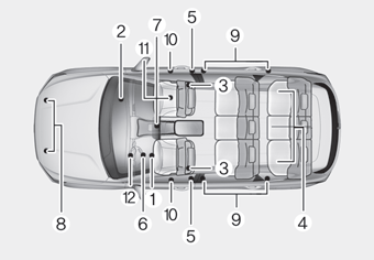
The SRS consists of the following
components:
1. Driver's front air bag module
2. Passenger's front air bag module
3. Side air bag modules
4. Curtain air bag modules
5. Retractor pre-tensioner
6. Air bag warning light
7. SRS control module (SRSCM)/
Rollover sensor
8. Front impact sensors
9. Side impact sensors
10.Side pressure sensors
11. Occupant classification system
12. Driver’s knee airbag module
read more